Thursday, November 22, 2018

Hatching a Plan


I'm enjoying a welcome relief from the sanding monkey mode as progress continues forward along the hull lengths.  This episode will require beginning with an image of an assembled part to understand the discussion to follow:


Above is a hatch that will provide ventilation through the forward bunk and a hatch mount.  The mount has radiused corners to match and accomodate the inside and outside hatch radiuses.  Box joinery provides a suitably strong connection between the mount's straight and curved sections.  The hatch mounting holes have been drilled out oversized and filled with epoxy to prevent water intrusion through the screw holes and to provide better holding power for the screws.  This mounting surface was later nicely flattened by working against sandpaper attached to the table saw surface.  


Above are all the parts for two hatch mounts shown with the box joint cutting jig.  A side piece is shown clamped to a jig that guides the work over the router bit within the red circle.  I enjoy an incremental fence with templates for easily creating box and other jointery.  The fence only moves in 1/32 inch increments so precise alinements with the templates are no problem when repositioning the work for the next cut.

In the foreground are three stages of producing a corner piece.  First is the blank followed by box joint cuts and finally the inside radius is cut.


The corner piece inside radius is roughed out on a band saw then mounted in a special jig to finish the inside radius.  The router bit is surrounded by a collar 1/8" larger in radius than the router bit.  The jig's base has a radius 1/8" larger than the desired finished part's radius.  The jig's radius rides against the collar to control the bit's cutting path.  

The bit is shown in the elevated position to make the final cuts.  The bit's cutting edge is not long enough to span the material's cut face and a lighter cut is easier on the set up.  For these reasons the initial cuts are made at half the material's height as shown on the corner piece.    The bit will tear out material if allowed to exit the work in the same direction as the bit rotation.  The cuts are only made partway past the center position to prevent tear out, then the part is flipped over to cut what was previously the upper uncut half.  The work's edge near the bit shows the upper burnt looking finished radius and the lower uncut section.  The next cut, on the end opposite the bit, will machine the part's upper radius face to the pencil line on the part's top and flush with the finished radius below.  
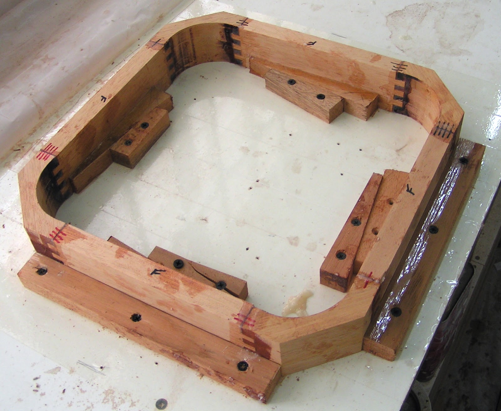

This fixture wedges the side pieces against stops that define the dimensions and keeps the assembly square as the epoxy cures.

When you build something, you know where all the warts are.  After cutting the first inside radius I did a trial fit of a corner piece with two side pieces against the hatch.  I judged it was necessary to increase the inside radius.  This unnecessary change reduced the corner sealing area width.  May I not suffer leaks as a result.


Plywood will sheath the deck.  The plywood must conform to the bulkhead curves and the shear sweep.  The installed hatch mount will stand proud of the deck about 1/4 inch.  In the image above the mount is lowered to clamp flush with stringers running between bulkheads.  This is to hold all the various pieces in the installed positions while not touching the fishing line stretched between the high points of the fore and aft bulkheads.  This set up is to determine the gentle curve just fore and aft of the mount.  These curves must be duplicated on the lumber held to the mount by the fore and aft yellow tipped spring clamps.  The deck sheathing will then have an attachment surface adjacent to the mount.

A spring clamp is removed and the lumber moved up until it just touches the fishing line.  Marks are made at the fishing line and at the positions against the stringer.  These three points determine the curve.


With sheet material the three points determining a curve can be laid out with protruding nails marking the points.  A batten pressed against the nails can be used to draw the curve.  The lumber was cut to length and left no room for nails.  An alternative method was devised as shown above.  Spacers are glued to the batton ends at a distance matching the work piece's length.  The spacers rest against a straight edge and a clamp bends the batten at the fishing line mark to create a curve.  The batten is aligned with the lumber stringer marks and the c clamp is tightened until the top edge of the lumber is just visible to draw the correct curve.  The curve radius can be adjusted over a range determined by the c clamp tension and the spacer thickness.


 The plans call for three, 3/4" by 1-1/4", stringers to run from this compartment and two additional compartments forward to the bow.  The hatch installed in this compartment requires an additional stringer, this should result in a stiffer deck.


Inside, under the hatch, will be retractable screens to provide shade or to exclude small creatures while allowing air flow.

Thursday, November 1, 2018

Decked Out


Completing the sanding on the aft two compartments has led to exciting developments in this area.  Above the mahogany aft deck stringers are fitted and resting on the deck beams.

The aft decks are fitted and attached to the stringers by screws.  Much work remains before the decks are epoxied in place.  The interior surfaces will receive two epoxy coats as well as paint before installation.  The light stringers create a deck that is too springy for my taste.  I'm considering an additional deck beam to better support the longer stringer span.  This led to an attempt to enter a hull and take some under deck measurements.  I placed a piece of lumber under the skeg so my weight would not over tax the hull rotation arrangement suspending the hull from the ceiling.  I climbed onto to a chair and placed one foot into the hull.  This quickly proved to be a less than wise idea as the hull started to rotate with my foot pressure.  A stupid accident story was averted.  Any additional deck beams will have to wait until the hulls are resting on cradles.  

Above is a view through two compartments forward of the dark aft bunk compartment.  These two compartments have the bulkheads tabbed to the hull panels with fiberglassed fillets.  Epoxy fillets are also applied on top of the stringers and along the sides of the butt blocks and backing pads.  The fillets on stringer tops will prevent condensation and debris from collecting in the lower hull panel end grain.  The butt block and backing pad fillets are just to give the hull a more finished appearance.  The above image shows the finished fillets and fiberglassed areas after three days of sanding.  Three days of sanding are ahead to bring the second hull to this state of completion.

Much of my time is spent sanding so I'm doing what I can to make it easier on myself.  I've made two radiused sanding tools to shape raw fillets and a small sanding block for flattening areas.  A piece of neoprene foam conforms to many shapes when wrapped in sand paper.  I've stock piled sandpaper cut to fit the various tools.  Initially the sandpaper was attached with hot glue, but this was not satisfactory and it took a while to change the sandpaper.  Staples are now used to attach the sandpaper.  A groove is cut under the areas where the staples are applied.  This arrangement keeps the staples below the sandpaper surface and prevents the staples from scaring the work.

Possibly my readers find all this talk of sanding tiring, I find it makes my fingers sore.  I've taken to wrapping my finger tips in tape so the bones don't start poking through.  Above is a fiberglassed fillet in the finishing process.  The area below my hand has been finished, the fiberglass edge is blended to the adjacent material while the surfaces are flattened and abraded for the painting to come.  A newly fiberglassed edge is lumpy with sharp skin tearing points that must be removed.  Great pressure and fine control are possible using the sanding block's smallest face to knock down the fiberglass edge.  The block is held at a slight angle to taper the fiberglass edge and blend it in.  Above my hand is an edge beginning in the tapering process.

With a few days of sanding I will have over half of the boat's compartments "finished".  The compartments ahead will be come more involved with designing and fitting two hatches in each hull.  It is likely only be a break from sanding rather than an end to sanding.

Tuesday, October 16, 2018

Then There Were Two

 
Above the upper hull panels are screwed onto the lower hull panels on the starboard (right) hull.  The hull panels are first screwed together to assure proper alignment.  Small plywood squares under each screw head prevent the screw heads from leaving large indents in the hull panels  The day to follow, my faithful helper and I will remove the upper panels and reinstall them with epoxy to bring both hulls up to a similar level of construction.  I found it exciting to have both hulls completed to this level.


At long last the massive epoxy stern fillets are completed and sanded in both hulls.  1 1/4" thick plywood forms the skeg's upper end and is embedded in the fillets.  Fiberglass will be applied over these fillets and then more sanding is in store.


Above the hull has been rotated on its' side facilitating sanding operations on seven fiberglassed fillets in the two aft most compartments.  Fiberglass is initially applied with straight epoxy and as the first coat starts to set up, a second coat is applied to fill the weave.  I add fairing (smoothing) compound to the second coat to ease the sanding following (I'm not sure if this is a recommended practice).  The aft most compartment is a flotation chamber that will rarely be viewed and I let slide the difficult to remove epoxy runs on the previously painted surfaces.   Two days were required to sand the seven fillets and two more sanding days are ahead on the second hull.  With this work completed, exciting progress on this area will come with the next episode.

Creature Comforts


Two years and four air beds later it is past time to invest in an actual bed.  This tall bed features eight drawers in the base and two in the headboard.  I like the fact that it has a modern edge to it rather than the frilly style most often found in Belize.  I don't know about the lime green sheets, but sheets are hard to come by and sometimes you can be happy to come home with anything at all.  I purchased the bed just before I had hernia surgery.  I returned from the hospital to learn it was much too painful to climb up into my new bed for a couple of weeks.  My mind has time to ponder a tall bed's possibilities in a bedroom recreational setting. 


Future guests will also be treated to a tall queen sized bed.  This bed features only four drawers in the base so no one stays too long.  The sheets for this bed came with an ordinarily useless blanket, but the house breaking for my "pet" geckos is not going well and a sheet shield is necessary.


Above is the new guest bathroom complete with light reading materials.  It actually is a composting toilet purchased for the boat.


Above are the inner workings of the composting toilet.  Basically the liquids are funneled into the orange colored hole.  The orange part is a float that rises as the container below fills.  The full container is lifted out and the attached white pipe swivels to form a spout for emptying the container.  The solids drop into a bucket filled with sawdust or other material that will dry the droppings.  A crank is inserted into the lid hole to engage the bucket agitator.  Ten turns on the crank and composting is underway.  No plumbing, wiring or odors are associated with this arrangement.  


I think most people have walked into a living room and found one television set in use on top of a broken set.  I have a different version of that as I have not been able to contact my gas guy for a refill so the stove and hot water services are not available for the present.  I've had breakfast at the resort across the street at US prices for a few mornings.  The poor guy needs some business as I've been the only customer.  This proved to be an opportunity to try out the boat's alcohol stove to great success.

Sunday, September 9, 2018

A Year's Progress

Late in August 2017 I paid for shipping marine plywood and epoxy from the U.S. to Belize.  As I recall this shipment was delivered to my address early in September 2017. This episode marks my first year of progress in the construction of a Tiki 26 catamaran.  Progress for the last two months has been hampered by a hernia and recovery from corrective surgery. My enthusiasm for the project has not waned, but I’m presently limited by what I can do.


This is a view forward from the port hull stern.  In the foreground is the aft floatation compartment followed by the aft bunk compartment with a tall bulkhead providing sitting headroom beyond.  Progress has been made in a number areas here.


A semi-rectangular opening is cut through the tall bulkhead to allow a large ice chest to slide into the aft bunk compartment.  The plans call for a circular opening that is far better in terms of load distribution. Below each end of the deck beam are plywood doublers strengthening the upper areas of the rectangular opening.  These doublers increase the plywood thickness from ¼” to 1\2” and will be joined to the hull/deck beams by a fiberglassed epoxy fillets.


I’ve ordered an opening portlight with fly screens for each hull.  These portlights feature an extruded aluminum frame and smoked acrylic glass.  A full sized paper cut out is taped to the tall bulkhead to judge the best portlight placement.  I think it needs to go a little left of the current position.


The aft most bullhead and the two foremost bulkheads (not visible) were trimmed in height to match deck beams flushed with the hull top edges.  The bulk of this work was accomplished using a router and a patterning bit to follow the deck beam curve. The aft most bulkhead posed the greatest challenge as when the aft deck beam edge is flush with the hull edges,  the forward deck beam edge is 1/16” high of the hull due to the shear (line formed at the hull/deck intersection) sweep. The bulkhead was initially flushed up to the high deck beam edge then a line was drawn down 1/16” down from the newly flushed edge.  A block plane was used bring the bulkhead down to the line and then to flatten the area from the new bulkhead edge to the opposite unmolested deck beam edge. The deck beam to deck face now follows the sheer sweep (or rocker).


The router was also used to open up the deck stringer landings in the aft most bulkhead.  Before long I’ll be fitting the deck stringers and decks. I intend to cut out most ¼” plywood parts before fitting the interiors with some of the scraps.  These parts would include the decks and the cabin sides. I have two extra ¼” plywood sheets in the event of errors.


Before any deck stringers are fitted, the stern fillet needs to be finished.  Above is shown the fillet lacking about three more inches of epoxy. The finished fillet will be about nine inches deep.  It can not be applied in one go as the epoxy heats up as it cures and large masses can heat up to the point of setting things on fire.  The epoxy must be applied in layers and allowed to partly cure before the next layer is applied and only a limited number of layers can be completed in a day.  When allowed to cure, the epoxy must be sanded, to assure good adhesion, before adding more layers.


I’ve purchased a two burner alcohol stove as a gally center piece.  Above I have mocked up a table arrangement utilizing a bunk locker cover.  This compartment will receive shelving and a sink for its’ gally function. A similar table arrangement in the starboard hull will serve for navigation purposes.


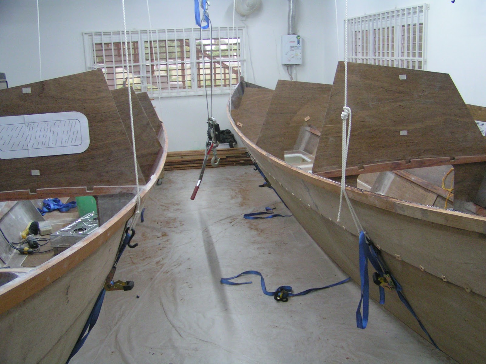
The hulls are suspended, fore and aft, from above.  On the right is the original suspension method with the hull resting in straps fixed above.  To rotate the hull, the strap has to slip across the keel and hull surface. This was fine until the weight and added dimensions of the upper hull panels were added and hull rotation became too difficult.

On the left is the new arrangement with the hulls still resting in slings, but the sling ends are attached to a rope passing through the green overhead sheaves.  The slings no longer work against the boat surfaces as the hull is rotated. A midships come along, suspended from above, is attached to a strap leading under the boat and anchored to the opposite hull edge.  Operating the come along lifts the hull as well as inducing hull rotation for those who are hernia tender.