Friday, September 30, 2022

Poof, Another Year has Passed

September 2022 arrives to mark this project's fifth year.  The worldwide shipping slow down and lack of available lumber has stymied my ambition to move the hulls outside and make provisions to mount the cross beams.  This is a phase in the project I'm excited to experience as it will give a scale to the project's finished size.  The lack of materials from the late shipment has prevented the last portlight from being installed so the port hull is not yet weather tight.  I've been scrounging for smaller jobs that have been put off for a while as a means to continue progress and to add refinements.

The gally sink drain plumbing is now complete.

The wiring for the port 12 volt and USB outlets as well as the gooseneck lamp is completed.  Some challenges were imposed by the heavy #10 wire used throughout the vessel.  The wooden outlet enclosure was just deep enough to allow the heavy wires to make the backside connections and bend as required to follow the wire conduit.  Solar cell leads were also installed in the conduit run used by the lamp and outlet.  The solar cells dictated the #10 tinned wires used throughout.  The large wire minimizes the voltage drop/waisted energy going into or from the battery.

Finishes

All the bunk locker panels received a sanding and two coats of varnish.  The varnish was applied over two epoxy coats.  The varnish protects the epoxy from sun degradation.  Varnish is so much easier than topside paint.  Note the two panels in the right foreground.  These panels are marked with a P and an S to denote port and starboard.  These two panels can serve as interior tables spanning the respective hull's width.  The panels' geometry and mounting fixture's fit vary enough that these panels must be identified.  These are the two panels with corner embedded magnets to securely stole the panels when not in use. 

The main hatches and wash boards receive two coats of high build primer on interior surfaces.  A new round of sanding awaits.... In a few months, cooler temperatures should give better topside paint results on these interior surfaces.

Companion Way, Washboards and Hatches

Above is the aft edge of the companion way opening.  The house (cabin) top slopes forward and towards the outboard side.  Any water leaking past the closed companion way is likely to collect in the corner and leak into the interior.  A groove is cut into the opening to encourage water to flow downhill and drain the corner.
The elevated washboard has been fitted with tapered projections that fit into the grooves when fully closed.
With the washboard seated and the hatch closed. the grooves are nearly filled by the projections.  The idea is that surface tension in the narrow space remaining in the grooves will help wick the water away.  It remains to be seen if this arrangement has any merit.
The washboard is hanging across from the companion way opening, but the real foreground subjects are the new ears located near the opening's top.  The ears help align the washboard edges into the grooves on either opening side.  
The hatch track is stamped from sheet metal and had many razor sharp edges offering chances of severe cuts.  The tracks were removed, and the edges received a rounding over with a file and 220 grit sandpaper.  The tracks were permanently installed by coating the screw holes with penetrating epoxy before inserting the screws.  The numerous track screw holes did not receive the normal arrangement of threading into an oversized, cured epoxy filled hole.  

Paint pulled off with the track and compromised the painted protection underneath.  Penetrating epoxy was applied to these areas to protect the underlying wood from water.  I would say the hatches slide better now than ever!

Crossbeams

The crossbeams, fore and aft of the cockpit, received two primer coats.  The mast supporting crossbeam is shown upside down in the background.

The mast crossbeam now sports a dolphin striker.  The dolphin striker counteracts the mast compressive forces imposed on the beam.  Above, the green fishing line shows the path a cable would take to anchors near the crossbeam ends.  Tension in the cable creates an upward force counteracting the mast's downward force.

3/4" x 3/4" lumber strips are applied at the underside beam opening ends.  Theses openings now present a flat surface around each opening.  This enables the use of flat screens to exclude nesting insects.  Bees have already made an effort to take over my bathroom sink cabinet.  It is good to pare down things that may cause worry.

The aft trampoline crossbeam web is in the foreground with the forward crossbeam web and bottom flange in the background.  Progress on the forward crossbeam is limited to epoxying a 3/4" x 3/4" stringer along the curving bottom flange edge.  The lack of suitable lumber to complete these beams has thrown a roadblock in moving this project outside for assembly. 

Mast

The beginnings of a mast.  A subscale PVC pipe stands in for the mast to show the component's relative positions.  The four, hook like, mast cleats are located near the mast top.  They provide anchor points for stays that loop around the mast and anchor to the outboard hull cleats as well as the forward hull bridal.  

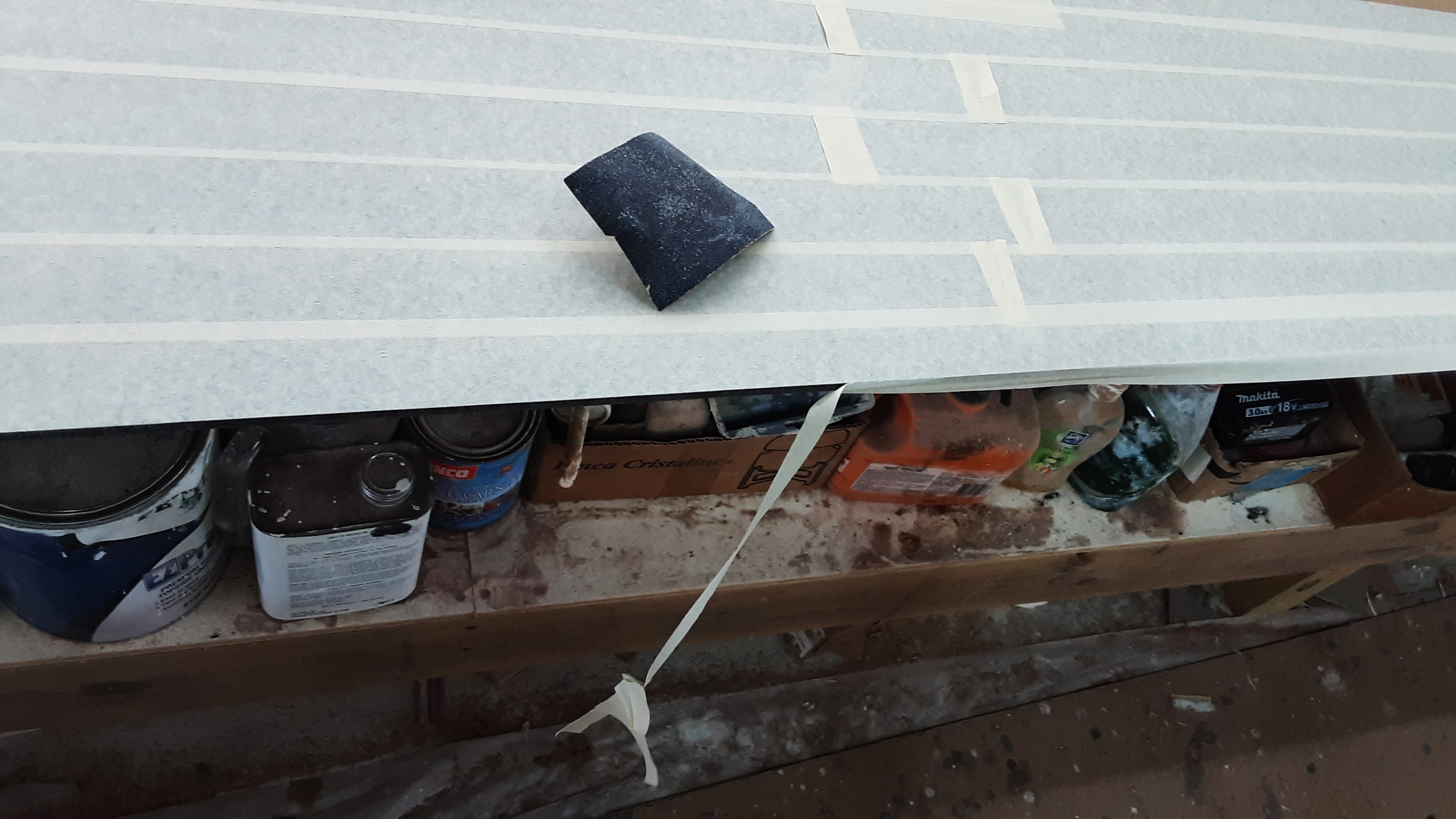
The hot dog bun shaped component is the gaff slider.  A gaff is a boom located at a sail's top or head.  The gaff slider slides along the mast as the gaff and sail is raised or lowered.  Leather is traditionally used on the sliding surfaces, but I used material cut from a plastic cutting board.  The plastic cutting board should provide a low friction surface and prevent scarring of a painted mast surface.  I've hung a sample of the cutting board material outside to test how it will endure the tropical sun for a year or so.  It remains to be seen if this is a good idea or not.

Step Ladder

In keeping with the desire to get this project outdoors, I built a step ladder for gaining access to the boat's interior and future cockpit.  In the foreground is a chair and a clamping worktable.  These items were my only means of obtaining boat interior access.  This arrangement has three steps to get to a level high enough to step inside.  The step ladder reduces the congestion at the narrowest point in the passage between the hulls.  I will not have to move my worktable and chair in and out of the weather in the future.

The top step received a modification to discourage its' use as an unstable step and to provide foot clearance when stepping into the hull.  The bulk of the step ladder's material is mahogany with scraps of my shipping crates thrown in.  The mahogany had too much undesirable sap wood to be used in the boat and took up floor space that I have reclaimed. 

I'm pleased to learn that the shipment departing Los Angeles August 8th should be in Corozal for distribution October 5th, hurricanes permitting.  There must have been problems along the way.  

Sunday, June 19, 2022

Boat Porn

Efforts are underway to close up the hulls so they can be moved outside to mount the crossbeams and other components.  Picking up from where the last episode left off .....

The aft cockpit beam is fiberglass covered and has received the first of many hand sandings.  Machine sanding can go wrong quickly and remove the newly applied fiberglass.  Part of the post fiberglassing sanding is to taper the overlapping fiberglass edges so that, with additional work, the beam will have a smooth, continuous, paint ready surface.

The beam's back and underside, with holes, has many inside corners.  It takes days to hand sand any one of the four beams.  The beam's back and underside are not readily visible and may not receive the top shelf paint treatment, but you may surely look forward to future whines about the sanding requirements.


A fiberglassed wooden cap has been constructed to exclude water from the depth transducer pipe mount.  

This is an early image of the cap construction.  A wooden ring is epoxied to scrap plywood.  An off cut from the transducer pipe mount rests inside the ring.  The off cut defines where this assembly must be cut to fit over the pipe mount and sit flush against the hull.  Two thickness of the off cut were cemented to the transducer pipe mount interior so the cap mounting screws had more material to thread into. 

The last shipment included three pairs of over center draw latches.  One pair was too large for this application, but may be used elsewhere.  Another pair was very attractive, but had a key lock that didn't look very substantial and a lost key could make for a bad few days.  The pictured draw latch will secure the house (cabin) sliding hatch with a combination pad lock.

The hatch end slides closed into a housing that could not be installed until the latch was selected and installed.  It is a happy day when loose pieces and loose ends are vanquished.

There was nothing to grab onto to open the sliding hatch.  Above and to the latch left is a new thumb nob correcting this condition.

I'm excited to share this image of the flush mounted portlights.  Unfortunately, this hull is too close to the wall to gain a perspective of how cool this looks.

The portlights  rest on a 1/4" thick bed of construction adhesive (Dow 795) applied to a one and one quarter inch wide internal flange.  The thick bed allows for the different rates of thermal expansion between the plywood and the plexiglass portlight.  Masking is applied around the opening's internal and external edges to keep the adhesive only where it needs to be.


  The portlight's internal face is masked, except for the perimeter edges that contact the adhesive.  The exposed contact edges are also sanded to improve adhesion, but I'm not sure this is necessary.  The adhesive is also used on glass, polished marble and other smooth surfaces that sanding might not affect.

The portlight's exterior face is also masked.  If  you ever have to mask to a sharp edge, leave the tape hanging over the edge then sand the edge with a fine sand paper to remove the over hanging tape.  This is a trick my father taught me in my younger days building model airplanes.  Boats and airplanes use identical terms for many components and are structured similarly.  Part of my training for this project comes from the many model airplanes I built in younger days.

Short lengths of lumber are super glued to the masked portlight.  The lumber extends past the portlight opening to rest on the house side, thereby flushing the portlight to the side.  Additional masking is individually applied under each piece of lumber so the lumber can later be removed without disturbing the underlying masking.  The white tape has better adhesion than the blue tape and it is used where ever the super glue is needed.  Small positioning blocks are glued to white tape below the lumber near each portlight end,  The lumber rests against the blocks to locate the portlight fore and aft as well as vertically.  

The house side is not flat and the portlight must twist and bend to sit flushly.  The blue ratchet straps apply force to the lumber and conform the portlight to the flush condition while the adhesive cures.

The construction adhesive has a 15 minute working time at 50% relative humidity.  The Belize humidity relative usually runs in the high 70% range or more.  I wait for a day when the humidity is near 60% to apply the adhesive.  Once the adhesive is applied and the portlight is held in positioned as shown, it is time (no time for dallying) to tool the interior adhesive squeeze out and remove the interior masking.  

The ratchet straps are removed when the adhesive is judged cured.  The exterior lumber masking and lumber is carefully removed without disturbing the underlying masking.  A 1/8" gap will be present between the opening and the portlight.  This gap is filled with an application of the construction adhesive then tooled before the masking is removed from the portlight and around the opening.  

A gap greater than 1/8" might be wise for climates with a temperature range greater than experienced here in Belize.  I calculated and expansion of 1/16" on the longest dimension over a temperature range of 40° F.  This means the gap at each end must accommodate a 1/32" change in dimension over the expected temperature range.  The cured adhesive (RTV) is a soft rubber like material able to change it's dimension +/- 50%.  I could not account for a temperature range/difference the smoked portlights might impose by insolation.  At worst, the gap adhesive may suffer, but the large flange surface area and thick bed should keep the portlights attached.  This will be put to the test when moved outdoors.

Portlight installation is a one shot deal and it has gone well with good results.  I under estimated the adhesive needed and await the next adhesive shipment to install the remaining portlight.

The hulls now sport the rectangular lashing pads that secure the crossbeams to the hulls and serve as anchor points for mast supporting stays. 

The twenty lashing pads require ...... sanding.  The lashing pads are through bolted to the shear stringer.  The bolt holes were drilled before the hulls were fiberglassed, so more than 60 holes had to be located again to penetrate the fiberglass covering. 


Wrapping fiberglass fabric around the pad's compound curved corners does not go well.  All the pads required fiberglass patches cut on the bias to provide a cure.  This cure required another round of .... sanding.  I exist to sand.

This boat porn image shows the port bow with some of the new hardware.  Are you excited now?  I am.

Wednesday, May 4, 2022

Seeking the Zen of Sanding

 The last episode pioneered presenting the completed component first, followed by discussions of the details.  This led to no great out cries and may contribute to comprehension of my efforts.

You may recall from the last episode that crossbeam progress was limited by the epoxy and lumber supply.  Two of the four crossbeams were constructed up to a point requiring vast quantities of unavailable epoxy.  The lumber shortage remains, but the epoxy shortage does not.  We'll pick up beyond where we left off.

Mast Crossbeam


This 14' 9" mast crossbeam will be located just forward of the cockpit.  It is the longest and most complicated of all the beams.  It has been enveloped in fiberglass and hand sanded.  The mast step is located on the beam's top center.  The step distributes the mast compressive loads onto the beam structure.  A dolphin striker, not yet installed, counters these compressive loads on catamarans.  To either side are semi-circular access ports located near the points where the beam is lashed to the inboard hull sides.  These ports allow access to anchor points for high strength synthetic line to pass through a hole, in the beam underside, to a centered standoff (not installed) three inches below the beam.   The line then returns inside the beam to attach to the opposite side anchor.  Tension on the line distributes the mast compressive forces to the hull attachment points rather like an upside down suspension bridge.

If you look carefully at each end you will find a cleat.  These cleats will be used for bumpers, springer lines and a future cockpit tent.  

I learned late in the process that the beam work was much easier on the saw horses rather than the bench.  I could access all sides and roll it over as required while completing the endless sanding seated.


The first task is to complete the five full length fillets along the beam's length.  These fillets reinforce the bonds between the 3/4" plywood web and other components as well as providing a smooth transition for laying fiberglass.  Of course these five full length fillets will require sanding by hand before fiberglassing is possible.  Here the yellowish fillet is reinforced with a three inch wide strip of fiberglass along its' length.  The gussets and other beam interior surfaces have received the finial coat of epoxy before a fairing will cover these surfaces.  Beam areas epoxied to the fairing are sanded as well.
  

Cutting out a fairing requires a template.  A strip of 3/8" plywood spans half the fairing width and is wire tied through gusset holes, conforming it to the fairing curve.  Small sticks are hot glued to the plywood to define points along the fairing edges.

In the first attempt at this, I used a piece of limber lumber that distorted when the wire ties were tightened.  This resulted in a fairing half that did not fit and I have no material for a redo.  I was lucky to find it could be made to work on the other end with some extra labor.


The template is laid on the fairing material and marks are transferred from the stick ends onto the material.  Nails are driven into these marks and a batten is clamped to the nails.  The batten creates a smooth curve that a line is drawn against to define a cut line.  


Works like a champ!


The fairing is faired.  Notice the outlined area on the lower left beam's end.  This wedge shaped area is a sixth epoxy fillet running the entire length.  It may have taken a week to complete as only so much epoxy can be applied and still maintain its' shape until it sets.  Of course sanding is required before each epoxy application.  I considered using wedge shaped lumber to fill much of the void, but thought it would be too much of a juggling act as the wedge and fairing are best adhered at the same time.  The wedge idea will be revisited on the next beam.


A early image of the inspection port and cover for the dolphin striker anchor.  The anchor is a 3/8" stainless steel bolt passing through two and one half inches of lumber to an imbedded nut.  As with all fastener holes, the holes are drilled over size and then filled with a high density epoxy.  The filled hole is then drilled to fit the fastener.  This arrangement prevents a pathway for water to enter the wood as well as provides better bearing surfaces for through fasteners and threads.  The inspection ports and covers received epoxy filled fastener treatments for all six cover retainer screws.


The first post fiberglass sanding in progress.  Hand sanding produces troublesome callouses where the finger nail edge meets the flesh.  My callouses from sanding the hull were just beginning to sluff off when I again had to seek the zen of sanding in the beam construction.  The taped up fingers offer some protection, but are not the hot ticket.  One taped finger tip I've learned is to use the regular cream colored masking tape as it will not unravel like the shown blue painter's tape.  This may be the first post fiberglass sanding, but not the last before the beam is fully completed.

Aft Crossbeam


Surely, some may find endless amusement in my trials by sanding.  I must soldier on to achieve the goal of beach bars and bikinis for evermore.  To that end, the 14' 4" aft cockpit beam construction is well underway.  The full length epoxy fairing fillet will soon be ready for shaping by sanding.  The wooden wedge filler idea was abandoned as the available lumber would not permit me to keep my fingers while making the cuts.

Painted Hulls


Then there were two...  Epoxy primer and top side primer arrived on a recent shipment.  This enabled the application of top side paint and antifoul paint on the starboard hull.  It has been unusually cool for late spring and early one morning I was able to apply one coat of topside paint that would flow out to a smooth finish.  Additional coats will be necessary, but that will have to wait for cooler times.  

The hull was inverted for the painting process.  It is always a dicey process inverting or righting a hull.  The hull suspension/rotation lines are beginning to show signs of fraying.  I hope I have inverted the hulls for the last time, but this may mean that at some point I'll be lying on my back and reaching up to sand a hull.  Ugh, where is the zen in that?

Saturday, February 12, 2022

Shortages

I thought my build descriptions might be clearer if I provided images and descriptions first of the end state, followed by details leading up to the end state.  If a person knows where a story is going, then it should be easier to recognize and understand the pieces in the detailed discussions.

The inverted starboard hull now sports a faired (smoothed) fiberglass sheathed hull with one coat of below the waterline grey epoxy primer and one coat of white topside primer.  I'll need more epoxy primer coats before applying three coats of antifoul black paint.  I ran out of the epoxy primer and moved the waterline masking so that I could begin applying the topside paint.  I applied one topside primer coat to discover more was needed.  I`ve been slacking on keeping the materials coming.  The shipping company shuts down for a month around the first of year and Belize now has a stevedore strike.  My hopes for applying topside paint before it is too hot for the paint to level out may be dashed.

The bare plywood hull first received fiberglass along the keel and skeg.  Later fiberglass is laid to cover each hull side while overlapping the keel.

The hull is faired and the waterline is masked off to receive the below waterline primer.  The rudder is temporarily attached so the waterline can be established on it as well.  To the right is a leveled batter board, a similar batter board is at the bow, at a prescribed vertical distances from the decks.  A fishing line tensioned between the batter boards can be positioned close to the leveled hull so that waterline defining points can be plotted along the hull's length.  A more complete description of this and the fairing process is given in a previous episode.

The keel under the chocolate colored areas received three layers of heavyweight 1708 fiberglass and a higher density fairing compound for improved abrasion  resistance. 

I enlisted the help of a neighbor friend to complete the laborious fairing job.  This includes applying and sanding three coats of epoxy fairing compound over the entire hull surface by hand.  I recruited the right guy as he is a sanding machine where I tend to sand less vigorously.

On the inboard hull side I've made provisions for a depth/fish finder transducer.  This black clothing iron shaped transducer is intended for transom mounting, but this hull doesn't really have a transom and the more traditional transducers use through hull fittings.  I don't like the idea of though hull fittings and it would not work with this hull and transducer shape.   The transducer could be mounted on a submerging pole, but that arrangement seems prone to damage.  This arrangement allows for transducer replacement while keeping the wiring protected.  In this case I would say, "There is no perfection, only compromise".

The transducer connects to a black box that transmits over WiFi and is compatible with my mobile, GPS position, tablet based chart plotter.  Other crew can download the phone app to maybe find a dinner fish.


The transducer cable runs through PBC pipe cut lengthwise so that the cable connector can pass between the hull and the pipe.  Below the waterline (above the blue tape) layers of thin wooden straps are epoxied to the hull and pipe section.  This builds up a ramp section forward and aft of the pipe that once faired and fiberglassed, hopefully produces a good hydrodynamic shape.

The transducer mount is built up from laminated 3/4" mahogany.  An adhesive will secure and seal the transducer to the mount.  Replacing transducer likely requires destroying it, which is of no consequence, if being replaced.

A heat gun conformed the pipe to the hull curve.  Sticks pressed against the wall forced the wooden laminations into the curving hull shape.

With my painting ambitions vanquished I determined I have enough materials to build two of the four crossbeams that tie the two hulls together.  This is nearly completed beam will locate just aft of the cockpit.  It is very similar to the longer mast beam forward of the cockpit.  This beam face will receive a 1/4" plywood fairing to complete the beam`s triangular cross section.  Many additional fillets will need to be made before the fairing can enclose this structure.  And that will have to wait until I'm epoxy rich again.

This beam side faces the cockpit.  The cockpit hangs on the beam`s lower ledge.

The beam cross section is like an I beam with a 3/4" plywood web and flanges made of 3/4" mahogany.   Note that the cockpit side has two thicknesses of mahogany.  Fillets are yet to be made that will strengthen the web and the thickened flange's bond. 

Here we see the beginnings of the beam`s underside.  The mahogany flanges are epoxied to the 1/4" plywood base leg.  The base is ventilated with wide rounded slots cut through the plywood to help prevent rot(?).  The base is wide in the center and tapers towards the ends.  This requires a large variety of hole sizes to be drilled between the flanges.  I am fortunate to have a fly cutter to cut large holes at fully adjustable sizes.  This single cutting point tool is seen chucked in the drill.  It can be a wild ride making a large hole with a single point tool using a hand drill, but no work was destroyed this round.  The slots are finished by means of a router patterning bit following the flanges to connect adjacent holes.

I wonder at leaving the slots open as africanized bees have been reported in my neighborhood.  The openings may make a good home for many undesirable creatures, but the incorporation of screens will wait for another time.

This is the beginning of the second beam construction.  This beam will be located forward of the cockpit and support the mast.  Here the second 3/4" flange is epoxied to the top surface of the beam's base and the curving 3/4" plywood web is clamped into position as epoxy cures. 

The beam's underside outboard ends will rest on locating blocks built into the hull.  The converging 3/4" flanges create a wedge shaped void above the locating blocks where water can become trapped and promote wood rot.  A wooden wedge shape now fills this void to avoid this potential failure mode and provides a suitable surface to mount locating blocks.

I enjoy construction of the new pieces, but I'm developing numerous loose pieces that can't be installed for various reasons.  The problem is where to put all the loose pieces and the increasing resemblance to a hoarder's home, with little pathways leading from one section to another.  If this condition should invade my upstairs living quarters, worry for me.