Showing posts with label Tiki 26. Show all posts

Saturday, March 15, 2025

Bimini Me Not


 I'm running out of things to build, but an amount of work remains in a large list of small and important things.

 Above is the gaff spar.  This is a spar at the top of the sail that increases the sail area while reducing the sail height.  The reduced sail height lowers the sail's center of force thereby reducing the capsizing forces.  This is an old school type of a sail rig.  The banana shaped piece will be held between the forks by a pin and slide against the mast as the gaff/sail is raised or lowered.  It is shown here after fiber glassing and primer painting.  I await the sails to install additional hardware and the paint top coat.


Each gaff leg is a lamination of three thickness of mahogany, it is just too stiff to bend in a single thickness.  The legs were individually laminated while clamped to blocks screwed into the work table to form the desired shape.  Above, the legs are epoxied together to complete the gaff.  This is followed by rounding over the edges to fit comfortably into the sail sleeve.   

I've always thought that a bimini would be necessary to provide refuge from the intense sun.  My thinking was that this would come as a later addition.  I happened to come across a bimini at a price and color that I could not pass up.  It is far easier to make provisions for this now rather than later.


Initially the bimini frame was too large to be accommodated in the available space and it made access into the cabins more difficult.  After much consideration and frame cutting it was made to fit, but the supplied bimini fabric top may be scraped.  The top will be a future project to develop sewing skills for other projects to come.  The bimini will provide coverage for over 50% of the cockpit area.  One down side is that the mast will need to be extended so the sail will pass over the bimini.  This has been done on other Tiki 26s.  I'll just need to reef the sail at lower wind speeds than in the standard mast configuration.


The bimini stows away in the forward position leaving the cockpit and mast operations unobstructed.  Reasonable access to the forward trampoline, lockers and head are possible by this arrangement.  The burgundy bimini cover still fits in spite of my modifications.


No, these are not tasty treats.  The ingredients are mahogany, fiber glass, epoxy and fairing compound.  These are the raw bimini mounting blocks before they are sanded and adhered to the cabin sides.   In the background is part of a full scale bimini frame drawing and its' hinge points.  This drawing was very useful in determining the frame cut lengths.

It was not possible to hold the floppy bimini assembly in the installed position without mounts.  Interference with other necessities were not apparent until the bimini was in position.  The sheets control the jib sail position and the bimini frame limited the paths the sheets could take to control the sail.  Crippling the boat's sailing ability is not a viable option.  Much time and effort went into the bimini, but this arrangement will be abandoned.  All is not lost as the bimini may reappear, but be more like setting up a tent at some future time.


Notice anything new and different here?  That's right, 140 watts of solar power installed on the locker lids!  Each solar panel has a dedicated solar charge controller to keep the battery charged.  If one panel is shaded by the sail, the other panel can still provide charge current.  A third charge controller is installed that may service a future panel on the aft trampoline.


One difficulty that had to be overcome was the very stiff solar panel lead wires.  These wires are meant to endure constant sun exposure and do not allow tight bend radiuses.  Above are the holes the wires pass through in the locker lid.  Initially a straight hole was drilled through the lid and then a small rasp was worked through the holes at an angle so the wires could be installed in a more horizontal position.  


The solar panels and lead penetration covers are held on by Very High Bond (VHB) doubled sided tape.  It is said that VHB tape is used to install windows in skyscrapers.  It is a one shot installation with no post installation adjustments.  To insure good alinement wooden locating guides are taped to the lid before installation.


Here the panel is installed with the lead penetration covers.  The covers are installed at a distance from the panel that gives the tightest lead radius that I feel comfortable with.  This image may better illustrate the need for the nearly horizontal lid penetration holes previously discussed.

It seemed wise to do some heavy boat material shopping as tariff stupidity is bandied about.  The following items should be in my hands in the next month or so:
- Main sail with burgundy gaff sleeve, sail cover, sail number 449 and inverted Wharram logo (for those two readers who know the boat's name)
- Jib sail with burgundy furling strips on the foot and leech
- Roller furling jib foil
- 100 Ah 12V lithium battery
- Locker latches
- Primer and paint 

Wednesday, January 31, 2024

Banjo Cases


Above is a start on the cockpit.  The material is honeycomb core fiberglass 4' x 8' panels.  Two panels were joined together with a mahogany spline to form the cockpit floor.  The floor was cut to finished dimensions of 77" x 96".  The sides are epoxied in place while clamped to keep everything square and straight. 

I don't enjoy working with this material as it has given me a case of fiberglass itch for the first time in this project.  Wearing flip flops and short sleeve shirts, while cutting this fiberglass material on a table saw says I was asking for a case of itch.

The panels came coated with white paint that did not stick well to epoxy so the paint had to be removed with a new belt sander.  The paint was removed where joins are made.  The paint was very difficult to remove, it must have been some great paint.


Cutting the panels slices through the honeycomb cells leaving voids in the cut surfaces.  The exposed cut surfaces can be filled with thicken epoxy to create a finished edge.

A person could look at the image above and wrongly ask, "Why the built-in banjo cases?"  I might look at the inquisitor askew and wonder how it is I come across as so hillbilly.

A pair of electric outboards will retract and fill the banjo cases.  There will be no visible indication that outboards are on board when retracted.  The battery placement is controlled by the power cord length extending from the outboard shaft.  I feel very lucky that the outboard equipment could be modified to suit my purposes.

A removable cover provides access to the retracted propeller in the event the anode needs changing, or the propeller needs to be cleared.  With the propeller lowered into the water and an improvised seat, this opening could serve as a backup to the composting toilet (may the day never come to pass).

These simple parts may not seem like much, but many concepts were conceived, rejected and iterated on to distill into the above parts.  These parts will mount the motor batteries and a motor control connector.

To the right is the underside of the battery case.  Battery case slots engage with the two smaller mounts to prevent fore and aft movement.

The single aft mount lifts the battery end 1.5 inches so that the motor lead exits the battery in a more horizontal position to better accommodate the limited vertical space,

The motor mounting screws are positioned about midway through the cockpit floor thickness.  The motor mount gives the motor a downward thrust of five degrees and retracts the propeller to a position too high for the available space.  The motor mount, above, overcomes these obstacles.

Here the motor mounts are seen in profile with wedges added on the aft (right) face.  The wedges assure that the motor shaft is 90° to the cockpit floor.  The mounts are epoxied to the underside edge of a cut out in the cockpit floor to form a shallow pan below the cockpit.

The finial cockpit form emerges with the addition of the inner locker walls.  The motors and batteries are contained in the lockers below the cockpit seats.  The width required for outboard installation and the adjacent batteries compelled a 22 inch width to the cockpit seats.  The seat width is too much for comfortable sitting but is better for laying down on.  The wide seat might be the perfect spot for a comfortable bean bag chair.

Fillets and fiberglass are applied along the length to the joined panels.  Gaining access to the joined surfaces is much easier with the cockpit resting on its' side.  


The inner combings (walls to block water from entering lockers) complete the cockpit's major construction.  Notice that fore and aft are square sections spanning between the right and left lockers.  The square sections carry wiring around the entire cockpit perimeter.  This wiring will provide for the following:
- anchor and navigation lights
- outboard motor control signals
- fore and aft 12V DC and USB outlets
- transfer solar and battery power between hulls
- depth sounder output and power
 
A coat of primer and the cockpit will be ready for fitting.

Possibly you recognize the person in the picture who is about to board his vessel for the first time.

A friend helped with the cockpit install, the images and celebration.  Regular readers may recall the four wheeled single axel dolly used to move the hulls.  Two 2"x4"s repurposed the dolly into a rickshaw like device to hold the cockpit at the correct elevation to rest on and between the crossbeams.  Clearance between the hulls and cockpit is about 1/2 of an inch.  I was rather astonished at how well this contrivance worked; I'm thereby encouraged to try any wild ideas that may occur to me.  


Looks like wanta be boater boy is pleased with the new perch.  Shortly after this picture, about 10:00 am, was the occasion for the first ever cockpit cocktails.  It turned into a pleasant cockpit day with a constant breeze, shade and new surroundings to contemplate.  


A contribution slot to Davey Jones locker exists between the cockpit and the hulls.  Anything on board is sure to fall through these slots.


The cockpit/hull gap is characterized with a template.


This filler plate should limit Davey Jones's take and block or reduce water splashing up between the hulls and the cockpit.  The locker lids will mount to the filler plate bolted to the inner combings.

Sunday, June 19, 2022

Boat Porn

Efforts are underway to close up the hulls so they can be moved outside to mount the crossbeams and other components.  Picking up from where the last episode left off .....

The aft cockpit beam is fiberglass covered and has received the first of many hand sandings.  Machine sanding can go wrong quickly and remove the newly applied fiberglass.  Part of the post fiberglassing sanding is to taper the overlapping fiberglass edges so that, with additional work, the beam will have a smooth, continuous, paint ready surface.

The beam's back and underside, with holes, has many inside corners.  It takes days to hand sand any one of the four beams.  The beam's back and underside are not readily visible and may not receive the top shelf paint treatment, but you may surely look forward to future whines about the sanding requirements.


A fiberglassed wooden cap has been constructed to exclude water from the depth transducer pipe mount.  

This is an early image of the cap construction.  A wooden ring is epoxied to scrap plywood.  An off cut from the transducer pipe mount rests inside the ring.  The off cut defines where this assembly must be cut to fit over the pipe mount and sit flush against the hull.  Two thickness of the off cut were cemented to the transducer pipe mount interior so the cap mounting screws had more material to thread into. 

The last shipment included three pairs of over center draw latches.  One pair was too large for this application, but may be used elsewhere.  Another pair was very attractive, but had a key lock that didn't look very substantial and a lost key could make for a bad few days.  The pictured draw latch will secure the house (cabin) sliding hatch with a combination pad lock.

The hatch end slides closed into a housing that could not be installed until the latch was selected and installed.  It is a happy day when loose pieces and loose ends are vanquished.

There was nothing to grab onto to open the sliding hatch.  Above and to the latch left is a new thumb nob correcting this condition.

I'm excited to share this image of the flush mounted portlights.  Unfortunately, this hull is too close to the wall to gain a perspective of how cool this looks.

The portlights  rest on a 1/4" thick bed of construction adhesive (Dow 795) applied to a one and one quarter inch wide internal flange.  The thick bed allows for the different rates of thermal expansion between the plywood and the plexiglass portlight.  Masking is applied around the opening's internal and external edges to keep the adhesive only where it needs to be.


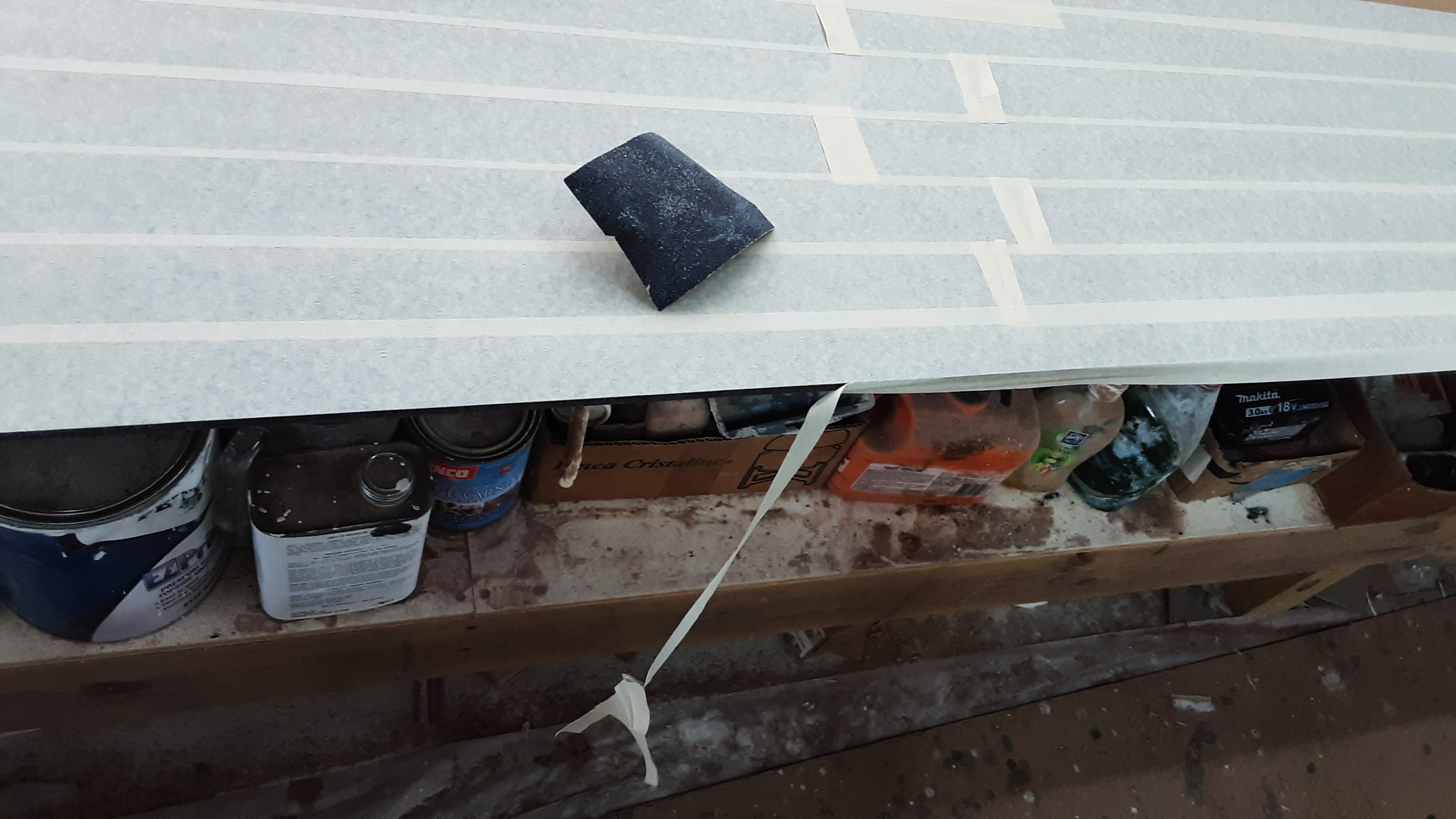
  The portlight's internal face is masked, except for the perimeter edges that contact the adhesive.  The exposed contact edges are also sanded to improve adhesion, but I'm not sure this is necessary.  The adhesive is also used on glass, polished marble and other smooth surfaces that sanding might not affect.

The portlight's exterior face is also masked.  If  you ever have to mask to a sharp edge, leave the tape hanging over the edge then sand the edge with a fine sand paper to remove the over hanging tape.  This is a trick my father taught me in my younger days building model airplanes.  Boats and airplanes use identical terms for many components and are structured similarly.  Part of my training for this project comes from the many model airplanes I built in younger days.

Short lengths of lumber are super glued to the masked portlight.  The lumber extends past the portlight opening to rest on the house side, thereby flushing the portlight to the side.  Additional masking is individually applied under each piece of lumber so the lumber can later be removed without disturbing the underlying masking.  The white tape has better adhesion than the blue tape and it is used where ever the super glue is needed.  Small positioning blocks are glued to white tape below the lumber near each portlight end,  The lumber rests against the blocks to locate the portlight fore and aft as well as vertically.  

The house side is not flat and the portlight must twist and bend to sit flushly.  The blue ratchet straps apply force to the lumber and conform the portlight to the flush condition while the adhesive cures.

The construction adhesive has a 15 minute working time at 50% relative humidity.  The Belize humidity relative usually runs in the high 70% range or more.  I wait for a day when the humidity is near 60% to apply the adhesive.  Once the adhesive is applied and the portlight is held in positioned as shown, it is time (no time for dallying) to tool the interior adhesive squeeze out and remove the interior masking.  

The ratchet straps are removed when the adhesive is judged cured.  The exterior lumber masking and lumber is carefully removed without disturbing the underlying masking.  A 1/8" gap will be present between the opening and the portlight.  This gap is filled with an application of the construction adhesive then tooled before the masking is removed from the portlight and around the opening.  

A gap greater than 1/8" might be wise for climates with a temperature range greater than experienced here in Belize.  I calculated and expansion of 1/16" on the longest dimension over a temperature range of 40° F.  This means the gap at each end must accommodate a 1/32" change in dimension over the expected temperature range.  The cured adhesive (RTV) is a soft rubber like material able to change it's dimension +/- 50%.  I could not account for a temperature range/difference the smoked portlights might impose by insolation.  At worst, the gap adhesive may suffer, but the large flange surface area and thick bed should keep the portlights attached.  This will be put to the test when moved outdoors.

Portlight installation is a one shot deal and it has gone well with good results.  I under estimated the adhesive needed and await the next adhesive shipment to install the remaining portlight.

The hulls now sport the rectangular lashing pads that secure the crossbeams to the hulls and serve as anchor points for mast supporting stays. 

The twenty lashing pads require ...... sanding.  The lashing pads are through bolted to the shear stringer.  The bolt holes were drilled before the hulls were fiberglassed, so more than 60 holes had to be located again to penetrate the fiberglass covering. 


Wrapping fiberglass fabric around the pad's compound curved corners does not go well.  All the pads required fiberglass patches cut on the bias to provide a cure.  This cure required another round of .... sanding.  I exist to sand.

This boat porn image shows the port bow with some of the new hardware.  Are you excited now?  I am.

Wednesday, May 4, 2022

Seeking the Zen of Sanding

 The last episode pioneered presenting the completed component first, followed by discussions of the details.  This led to no great out cries and may contribute to comprehension of my efforts.

You may recall from the last episode that crossbeam progress was limited by the epoxy and lumber supply.  Two of the four crossbeams were constructed up to a point requiring vast quantities of unavailable epoxy.  The lumber shortage remains, but the epoxy shortage does not.  We'll pick up beyond where we left off.

Mast Crossbeam


This 14' 9" mast crossbeam will be located just forward of the cockpit.  It is the longest and most complicated of all the beams.  It has been enveloped in fiberglass and hand sanded.  The mast step is located on the beam's top center.  The step distributes the mast compressive loads onto the beam structure.  A dolphin striker, not yet installed, counters these compressive loads on catamarans.  To either side are semi-circular access ports located near the points where the beam is lashed to the inboard hull sides.  These ports allow access to anchor points for high strength synthetic line to pass through a hole, in the beam underside, to a centered standoff (not installed) three inches below the beam.   The line then returns inside the beam to attach to the opposite side anchor.  Tension on the line distributes the mast compressive forces to the hull attachment points rather like an upside down suspension bridge.

If you look carefully at each end you will find a cleat.  These cleats will be used for bumpers, springer lines and a future cockpit tent.  

I learned late in the process that the beam work was much easier on the saw horses rather than the bench.  I could access all sides and roll it over as required while completing the endless sanding seated.


The first task is to complete the five full length fillets along the beam's length.  These fillets reinforce the bonds between the 3/4" plywood web and other components as well as providing a smooth transition for laying fiberglass.  Of course these five full length fillets will require sanding by hand before fiberglassing is possible.  Here the yellowish fillet is reinforced with a three inch wide strip of fiberglass along its' length.  The gussets and other beam interior surfaces have received the finial coat of epoxy before a fairing will cover these surfaces.  Beam areas epoxied to the fairing are sanded as well.
  

Cutting out a fairing requires a template.  A strip of 3/8" plywood spans half the fairing width and is wire tied through gusset holes, conforming it to the fairing curve.  Small sticks are hot glued to the plywood to define points along the fairing edges.

In the first attempt at this, I used a piece of limber lumber that distorted when the wire ties were tightened.  This resulted in a fairing half that did not fit and I have no material for a redo.  I was lucky to find it could be made to work on the other end with some extra labor.


The template is laid on the fairing material and marks are transferred from the stick ends onto the material.  Nails are driven into these marks and a batten is clamped to the nails.  The batten creates a smooth curve that a line is drawn against to define a cut line.  


Works like a champ!


The fairing is faired.  Notice the outlined area on the lower left beam's end.  This wedge shaped area is a sixth epoxy fillet running the entire length.  It may have taken a week to complete as only so much epoxy can be applied and still maintain its' shape until it sets.  Of course sanding is required before each epoxy application.  I considered using wedge shaped lumber to fill much of the void, but thought it would be too much of a juggling act as the wedge and fairing are best adhered at the same time.  The wedge idea will be revisited on the next beam.


A early image of the inspection port and cover for the dolphin striker anchor.  The anchor is a 3/8" stainless steel bolt passing through two and one half inches of lumber to an imbedded nut.  As with all fastener holes, the holes are drilled over size and then filled with a high density epoxy.  The filled hole is then drilled to fit the fastener.  This arrangement prevents a pathway for water to enter the wood as well as provides better bearing surfaces for through fasteners and threads.  The inspection ports and covers received epoxy filled fastener treatments for all six cover retainer screws.


The first post fiberglass sanding in progress.  Hand sanding produces troublesome callouses where the finger nail edge meets the flesh.  My callouses from sanding the hull were just beginning to sluff off when I again had to seek the zen of sanding in the beam construction.  The taped up fingers offer some protection, but are not the hot ticket.  One taped finger tip I've learned is to use the regular cream colored masking tape as it will not unravel like the shown blue painter's tape.  This may be the first post fiberglass sanding, but not the last before the beam is fully completed.

Aft Crossbeam


Surely, some may find endless amusement in my trials by sanding.  I must soldier on to achieve the goal of beach bars and bikinis for evermore.  To that end, the 14' 4" aft cockpit beam construction is well underway.  The full length epoxy fairing fillet will soon be ready for shaping by sanding.  The wooden wedge filler idea was abandoned as the available lumber would not permit me to keep my fingers while making the cuts.

Painted Hulls


Then there were two...  Epoxy primer and top side primer arrived on a recent shipment.  This enabled the application of top side paint and antifoul paint on the starboard hull.  It has been unusually cool for late spring and early one morning I was able to apply one coat of topside paint that would flow out to a smooth finish.  Additional coats will be necessary, but that will have to wait for cooler times.  

The hull was inverted for the painting process.  It is always a dicey process inverting or righting a hull.  The hull suspension/rotation lines are beginning to show signs of fraying.  I hope I have inverted the hulls for the last time, but this may mean that at some point I'll be lying on my back and reaching up to sand a hull.  Ugh, where is the zen in that?