I am highly surprised to learn that most readers of this blog live in Brazil. I have no idea of how that came to be and would be interested to read any comments on this matter.

The three major crossbeams have received tabs on the underside that will later be drilled to lace on the trampolines. A little more priming and the crossbeams will be ready for ......

Some sanding, masking, painting and hardware mounting bring the crossbeams into a state of readiness for installation on the hulls.

The hulls must be lifted onto the dolly to move them outside. In the previous experience with this, the dolly wheels appeared to be overloaded. Two additional wheels were added to the dolly to better handle the load.

Pad eyes are installed along the hull's inboard edges as part of the trampoline lacing system.


Here the crossbeams are placed in position on the hulls under a sunscreen. A good friend was very helpful extracting all this from the shop as well as erecting the sunscreen. The forward crossbeam has lashings on the outboard ends to secure the crossbeam to the hull. There is a shortage of lashing lines for the inboard and outboard positions on the remaining crossbeams.
The shop is so much roomier now with all this moved outside.

This is the control panel for the dual electric outboards. This control panel will be mounted inside the starboard hull near the companion way. A person may operate the motors from inside the hull or from the cockpit.

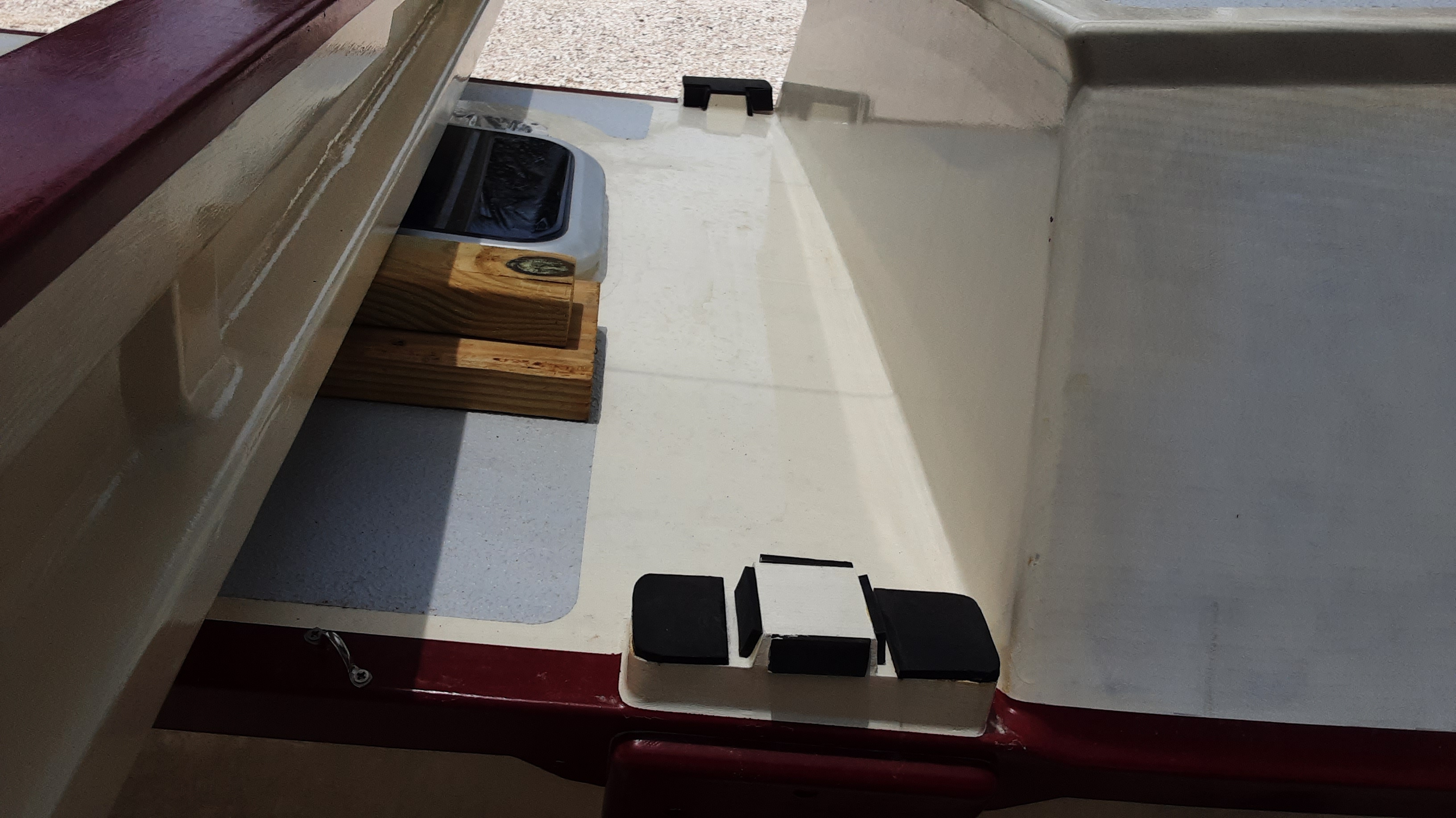
I've repurposed the outboard shipping box as a mockup of the outboard cockpit installations. The outboards will reside in cockpit seat/lockers located along the inboard side of each hull. The seat/lockers will extend to the full eight-foot cockpit length, a length longer than the shipping box. The box width is about right to accommodate both the outboard and the battery.
The box bottom is cut out to allow the propeller and shaft to be tilted down into the water. A wall will follow the cutout edge and a cover over the propeller and shaft will prevent water entry. Two episodes ago (The Light of Day) the outboards were shown in their normal configuration with the battery mounted on the outboard shaft top. This would not work for my application and the battery mount was cut off from the shaft. No doubt this voided the warranty, but the warranty will run out long before these motors see the water. The cutting provided a means to mount the battery within the locker as well as the only thing preventing the outboard from dropping into the ocean is the black shaft clamp located above the tilting mechanism. The lack of the battery counterweight makes it difficult to lift the shaft and propeller from the water. Some lever arrangement must be worked out to overcome this issue.
Partly visible at the image top is a cardboard outboard mockup. This was much easier to hold up near a hull to work out any issues.

I think the color combinations are working out well and I had to include a little boat porn. Some may mistakenly think this project is nearing completion. The truth is there is there is much work left to do, but I may have completed the most time consuming and difficult parts at this point.