Hatching a Plan
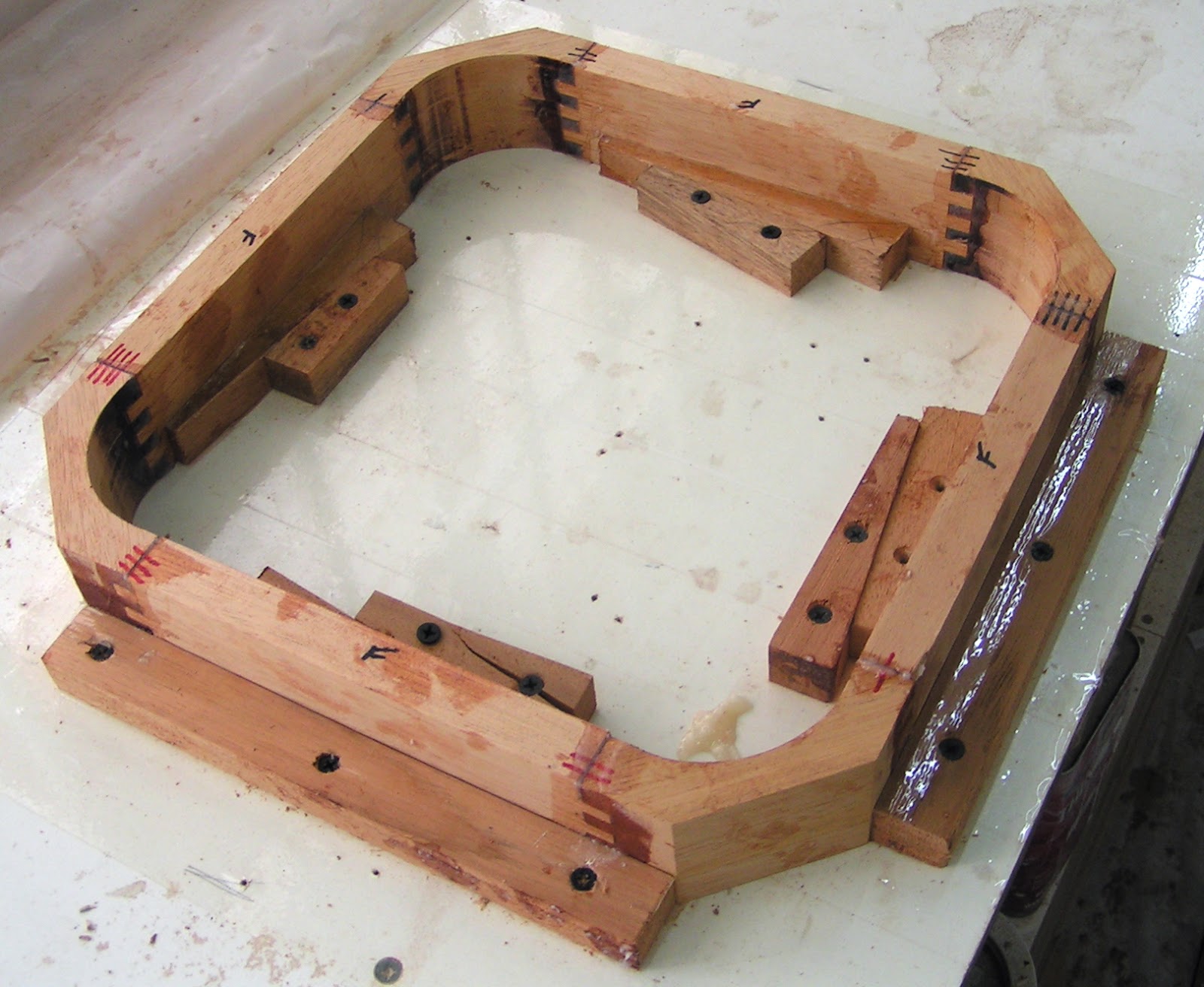
I'm enjoying a welcome relief from the sanding monkey mode as progress continues forward along the hull lengths. This episode will require beginning with an image of an assembled part to understand the discussion to follow:

Above is a hatch that will provide ventilation through the forward bunk and a hatch mount. The mount has radiused corners to match and accomodate the inside and outside hatch radiuses. Box joinery provides a suitably strong connection between the mount's straight and curved sections. The hatch mounting holes have been drilled out oversized and filled with epoxy to prevent water intrusion through the screw holes and to provide better holding power for the screws. This mounting surface was later nicely flattened by working against sandpaper attached to the table saw surface.

Above are all the parts for two hatch mounts shown with the box joint cutting jig. A side piece is shown clamped to a jig that guides the work over the router bit within the red circle. I enjoy an incremental fence with templates for easily creating box and other jointery. The fence only moves in 1/32 inch increments so precise alinements with the templates are no problem when repositioning the work for the next cut.
In the foreground are three stages of producing a corner piece. First is the blank followed by box joint cuts and finally the inside radius is cut.

The corner piece inside radius is roughed out on a band saw then mounted in a special jig to finish the inside radius. The router bit is surrounded by a collar 1/8" larger in radius than the router bit. The jig's base has a radius 1/8" larger than the desired finished part's radius. The jig's radius rides against the collar to control the bit's cutting path.
The bit is shown in the elevated position to make the final cuts. The bit's cutting edge is not long enough to span the material's cut face and a lighter cut is easier on the set up. For these reasons the initial cuts are made at half the material's height as shown on the corner piece. The bit will tear out material if allowed to exit the work in the same direction as the bit rotation. The cuts are only made partway past the center position to prevent tear out, then the part is flipped over to cut what was previously the upper uncut half. The work's edge near the bit shows the upper burnt looking finished radius and the lower uncut section. The next cut, on the end opposite the bit, will machine the part's upper radius face to the pencil line on the part's top and flush with the finished radius below.
This fixture wedges the side pieces against stops that define the dimensions and keeps the assembly square as the epoxy cures.
When you build something, you know where all the warts are. After cutting the first inside radius I did a trial fit of a corner piece with two side pieces against the hatch. I judged it was necessary to increase the inside radius. This unnecessary change reduced the corner sealing area width. May I not suffer leaks as a result.

Plywood will sheath the deck. The plywood must conform to the bulkhead curves and the shear sweep. The installed hatch mount will stand proud of the deck about 1/4 inch. In the image above the mount is lowered to clamp flush with stringers running between bulkheads. This is to hold all the various pieces in the installed positions while not touching the fishing line stretched between the high points of the fore and aft bulkheads. This set up is to determine the gentle curve just fore and aft of the mount. These curves must be duplicated on the lumber held to the mount by the fore and aft yellow tipped spring clamps. The deck sheathing will then have an attachment surface adjacent to the mount.
A spring clamp is removed and the lumber moved up until it just touches the fishing line. Marks are made at the fishing line and at the positions against the stringer. These three points determine the curve.

With sheet material the three points determining a curve can be laid out with protruding nails marking the points. A batten pressed against the nails can be used to draw the curve. The lumber was cut to length and left no room for nails. An alternative method was devised as shown above. Spacers are glued to the batton ends at a distance matching the work piece's length. The spacers rest against a straight edge and a clamp bends the batten at the fishing line mark to create a curve. The batten is aligned with the lumber stringer marks and the c clamp is tightened until the top edge of the lumber is just visible to draw the correct curve. The curve radius can be adjusted over a range determined by the c clamp tension and the spacer thickness.

The plans call for three, 3/4" by 1-1/4", stringers to run from this compartment and two additional compartments forward to the bow. The hatch installed in this compartment requires an additional stringer, this should result in a stiffer deck.

Inside, under the hatch, will be retractable screens to provide shade or to exclude small creatures while allowing air flow.
Hi Don. I am impressed by your attention to detail, and appreciate your willingness to share the same. It reminds me that anything created, with function or form, requires intelligence, planning and effort. Nothing “just happens”. Thanks again for the updates, allowing the rest of us to enjoy the journey. Keith
ReplyDelete