Saturday, April 20, 2019

A Major Wart


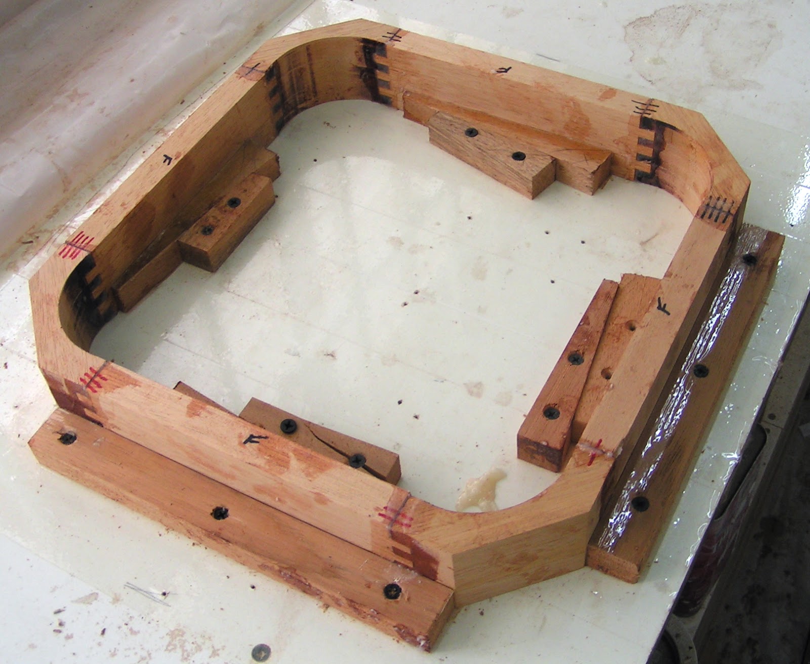
At long last; the nine inch deep bow fillets are completed and fiberglassed.  These were the last major structural fillets to complete in the hulls.  The lumber clamped inside the hull will later receive screws to mount chocks protecting anchor and docking lines from worrying against the shear (edge defined by the hull and deck intersection).


Above, the ventilation hatch mount subassembly is epoxied together in stages.  This required clamping and installing the loose pieces in the hull and verifying the mount is properly located to extend through the hole previously cut in the deck sheathing.   With the deck removed, c-clamps securing the mount on the longitudinal deck stringers; the short deck supports are epoxied to the mount's fore and aft sides.  At the stage above, the short deck supports and one edge of the mount are epoxied to a longitudinal stringer.  Clamped on legs support the assembly in position while epoxing on the remaining longitudinal stringer.  This staged in situ approach allows the fit between mating parts to be checked and adjusted for correct alinement. 


The boat will have modist electrical needs.  I've estimated a 100 ampere hour battery will suit my purposes.  I'm considering a lithium iron phosphate battery as apposed to a lead acid battery.  For a long life; the lead battery can only be discharged to 50% of its' rated capacity where a lithium battery can go to 20%.  The lithium battery is lighter at 30 pounds, endures a greater number of charge cycles, requires no maintenance, is free of flammable gases and acid, but comes with a hefty price.  As I often say, "For every pleasure there is a pain".

A plywood mock up of the battery is shown in the above view aft along with the battery shelf and the locker areas where the paint is removed so the shelf can be epoxied in place.  It was a real treat on a breezeless hot day, hanging over the bunk edge, blood pooling in the head while reaching down and back to remove the paint.  I discovered late in this process that a sharp chisel is about the best tool to scrape away the paint.  It also reaffirmed the lesson to mask off known painted areas subject to later gluing.  Prior to building the battery mock up I considered placing the battery in the aft bunk compartment or a cockpit locker, but there were complicating negatives to these locations.


Here we see the "battery" resting on its' shelf and completely tucked away beneath the forward bunk overhang.  The short battery cables will pass through a hole in the bulkhead behind and then up to an electrical distribution panel to be installed above and to the left in the companionway (entrance to the boat's interior) compartment aft.  Short wire runs will complete electrical connections between the solar charge controllers and the battery.  All of this with good battery access.


My focus is to complete all the interior work necessary to install the front and rear decks.  To that end the forward locker, the bow and stern flotation chambers have received top side paint.


The starboard forward locker has received paint in the lower portion and a floor for the head.  The white PVC pipe is electrical conduit to take power leads from lid mounted solar cells aft, through two compartments, to the companionway electrical distribution panel.  A similar arrangement exists in the port hull.


The composting toilet covers the head floor hole.  In the foreground are two latches that will secure the lid over the inner combing (elevated box surrounding the hatch opening).  The rotating latch arms will be joined by a link that is pulled, by means of a hole in the bulkhead (lower right), to engage dogs on the lid underside.  This provides a method to lock up the forward lockers from inside the boat without the need for locks or keys.

Space is limited in the open air head and I regret opting for the elongated seat.  This seat could invite wet accidents as well as reducing the available footing room.  It is an 18 inch step down from the combing lip to the head floor.  This could make for failed entry and exit tales.  A midway step seems wise.


Straight, level and square do not seem to be the character of a boat.  This poses challenges in laying out and sizing new structures.  The best that can be expected is flat as a reference surface to derive other locations needed for new fitments.  Above, the step elevation is marked with blue tape at points along the bulkhead and hull as indicated by the pointed stick.  This shaky set up can rest on the flat surface and reach out to the sloping hull sides to indicate the step elevation.  It was easily checked against the first piece of tape applied to assure it indicated correctly.


The step is fitted to the bulkhead and hull.  Underside cleats support the step that will be installed after painting an otherwise difficult to paint corner.  It is held up by a prop rod used only for the purposes of making this image.  The step features a toe stop to protect the electrical conduit.  The step protrudes minimally into the space directly below the hatch opening.  

The hatch lid will hinge on the same side as the step.  The lid must be restrained in the open position by a locking linkages to prevent the wind from blowing the lid closed on an unfortunate occupant.  These linkages are likely to attach midway on the fore aft inner combing ends.  The best hope is that a person of short stature will not suffer a crotch to linkage impact when using the step.  A locked linkage will enable the lid to be used as a steadying influence when entering or exiting in my best case scenarios. 


The above image shows the deck and the forward house (cabin) bulkhead.  In the lower right is a white piece of tape with a pencil mark.  The pencil mark indicates where the forward bulkhead face should be, 7/8" aft of where it is.  This mistake means that the length of a plywood sheet is too short to span the house length as intended.  A crossbeam lands directly in front of this bulkhead and would require a much larger crossbeam to house gap on the starboard hull and a tapering gap on the port hull.  This compounds into issues mounting the cockpit that are best avoided.  It is embarrassing to make such a mistake and it is a wart that must be removed.

The tool above oscillates a fine kerf saw blade that cuts the bulkhead flush at the deck surface.  I previously had a Porter Cable version of this tool I chose not to bring with me.  The tool was big and heavy while providing great effort and frustration in changing out the oscillated tooling.  This german Fien tool is a jewel in comparison.  Flip a lever to drop a tool and just pop the next tool on.


A tapered shim spans the bulkhead width to correctly position the house bulkhead.


Above, the epoxy sets on the butt block joining the house bulkhead to the tapered shim.  Happily this correction went exceptionally well with the bulkhead lining up on the marks.

I'm enjoying fitting out the interior that is not detailed in the plans.  The most difficult part is anticipating what fixtures are necessary for living extended periods on a boat.  Then comes the simplification and innovation necessary to achieve hopefully elegant solutions.   Meanwhile, the backlog of parts requiring epoxy coating, sanding, painting, sanding and sanding continues to grow along with the piles of sand dust.

Scooter Blues


The long awaited scooter I received in February is still not legal for road operation.  I've added turn, running and brake lights as well as a horn.  The LED turn signal/running lights required a special flasher relay that recently arrived, but failed to produce the necessary blinking.  I've read that load resistors are sometimes installed to make the flasher work.  Not having load resistors, in a flash of brilliance (puns intended) I reasoned ordinary incandescent bulbs could be used to provide the necessary load.  Sure enough the flasher operated the LED turn signals with the load bulb in the circuit, but the LED running lights, built onto the same circuit board as the turn LEDs, no longer operated.  Presently, the scooter remains disassembled and unable to pass inspect for road operation.  I await an adjustable LED flasher relay that may provide a solution to my scooter woes.  It should arrive in about two months.


Thursday, March 14, 2019

The Pecker Birds


My sleeping habits have changed to where I'm generally up at 3:30 am for some unknown reason.  About the time the sun is coming up, I've experience a tap, tap, tapping.  Investigating the source of this noise I discover a beautiful reddish orange and black bird pecking away at the pickup windows and mirrors.  This bird is extremely skittish and would flit away at the slightest of my motions on the deck above.  This bird was soon replaced by the pecker bird shown below and the beautiful bird was rarely seen again.


The pecker bird was not skittish at all and would allow a very close approach while giving me a look that said; "yeah, so what ....?"  With that I initially agreed, after all what harm could this pecker do?  There is the issue of this bird's droppings coating the doors, mirrors and bed sides.  This additional indignity may be fitting for a vehicle designed not to impress on any level.

I allowed the little pecker to have at it for a while.  At times he would really get worked up and go to town on the windshield.  This went off and on throughout the day, until I noticed the little pecker was creating pits in the windshield.  I've experienced the persistence of birds when herons return year after year to fish my koi ponds.  I assumed breaking the pecker behavior would be difficult, but no!  Two encounters with well thrown rocks diverted his pecking to the neighbor's window.  Now the skittish beautiful bird is back at it.

In my previous life I enjoyed automobiles intended for spirited driving on twisting roads.  Such vehicles are not suitable or enjoyable on Belize roads.  I do not find enjoyment in driving a low powered, lumbering pickup under any conditions, but it suits the circumstances.  I think I've found a solution to my first world problem:

Scooter Porn


This pothole doger is an electric Phat Scooter.  It has a top speed of 20 mph and a range of 30 to 50 miles.  It features front and rear hydraulic disk brakes as well as front and rear suspensions.  In most parts of the U.S. this scooter is allowed to operate on bicycle trails with no license or title requirements.  After purchasing the scooter I had this Dorthy in the Wizard of Oz moment when I realized was no longer in Kansas.  The scooter needs to be titled and licensed in Belize.  This would require the addition of a horn, brake light and turn signals as well as switches to control these items.  I set to work with the parts I could obtain locally from the chinese scooter dealer.

A switch housing was fitted next to the left handlebar grip.  The switch housing grips the handlebars in an area deformed by the nearby bend.  Some file work on the housing gripping surfaces accomodated the handlebar deformations.  The electric horn is visible behind the front fender.  Just below the switch housing is a squeeze bulb horn.  It is one of those horns where the body tube loops just before the bell.  I like to call it my Happy Hello horn as apposed to the Clown Horn description it is sold under.  

 The turn signal/running lights and handlebar mounting clamps I ordered on line.  These mounting clamps are ordinarily used to attach rear view mirrors.  The clamps were drilled and tapped to accept the light mounting threads.  The electrical leads exit an additional drilled hole.  


The rear turn signal mounting brackets were recycled from the light angle iron shipping cage protecting the scooter.   The center brake light was sourced locally.  I built the black wooden forward section to give it a teardrop profile.  I may change this taillight out in the future.

It has been a fair amount of work figuring out how to modify and implement the wiring.  Everything works with the exception of the turn signals.  The LED lights require a special flasher relay that I will not have until the next shipment arrives in the middle of April, a month away.  Along with the relay I will be receiving a new saddle shaped seat suspended by springs to better tame the potholes.

This scooter will serve the majority of my transportation needs.  I have a large light fabric bag that will hold cargo on most shopping expeditions.  I have been very excited to receive this scooter and the returning driving pleasures.  The scooter sat at the freight forwarders in Los Angles since early December and I did not receive it until the middle of February.  Presently lacking turn signals I can not yet register it for use on the road.  Is scooter gratification delayed scooter gratification earned?  

I will admit to taking illicit scooter rides in the neighborhood to make these observations.  An early ride took me on a road I don't often travel.  This resulted in a higher speed scooter encounter with a monster pothole.  This was a good early lesson for me as I required chiropractic services shortly thereafter.  The on order, spring suspended, seat will be a grand improvement over the inadequate stock seat.   I was expecting a greatly cushioned ride on the wide tires inflated at 10 psi rather than the recommended 15 to 20 psi.  A higher tire inflation pressure will improve the range and may make it less squirrely on rutted road sections.  The wide tires makes it possible ride at what would otherwise be impossibly slow speeds.  The 1200 watt motor has torque for effortless hill climbing and good acceleration.  The three speed ranges (8, 13 and 20 mph) are very useful to reduce throttle authority in lower speed situations.  20 mph may be as fast as I'll ever want to go on this scooter as the sensation of speed is great!  The reactions of the few people that have seen this scooter have been unusually positive.  This would be great if I were more comfortable in the spot light.

The Boat Build

I've had two weeks of visitors merged with a good three weeks of a lingering illness overlapping the scooter receipt and modifications.  Yet there is previous and present build progress to report.  Earlier efforts have produced many parts comprising deck stringers, decks, hatch mounts, and hatch combings.  With all these loose parts things were becoming chaotic.  It was time to assemble some parts and restore order.


Above the deck stringers are epoxied to the rear deck undersides.  Two coats of epoxy were applied to these components followed by sanding before assembly.


Laid out on the sawhorses is the underside of the forward deck subassemblies.  Two plywood sheets makeup the forward deck.  These sheets are joined by butt blocks visible to either side of the forward hatch cutout.  The sheets will be joined as part of the on hull installation process.  These subassemblies also received the protective epoxy coating and sanding treatment.  


The forward hatch inner coamings received an outside 1/4" overhanging lip to help exclude water from the inside.  Coamings are surfaces intended to exclude/deflect water.  The hatch lid will extend over the inner coaming to close against the outer coaming.  The outer coaming face, seating against the hatch lid, is just above the deck surface.  Thus, any water forced pass gaps in the outer coaming will be directed against the side of the inner coaming and further inhibited from entering the vessel by the hatch opening outside lip.  This is one traditional method of building water tight hatches.


 Above are inwale timbers clamped in the starboard hull stern glue up.  These inwales assure substantial material is available to receive screws supporting the aft trampoline and hardware to tie up the boat.

  
The bow ends are also receiving inwales to support the forward trampoline.   The inwales start out with rectangular cross sections.  When they are clamped to the sloping hull sides, a one edge protrudes above the surface the deck must rest on.  The protruding edge is planed down so the deck underside is in good contact with the inwale and provides good footing for future screws.

The head floor is visible in the left compartment.  The composting head covers the opening providing access below, but normal access is through the cover to the right.


My next task is to finish up the bow fillets.  The bow fillet above has been sanded in preparation for building up with additional epoxy applications.  It is not wise to fill this volume in one go as large epoxy volumes generate significant heat during the curing process with the potential for fire.  The epoxy is applied in thinner layers that generate less heat.  Once a layer has partially cured another layer is then applied.  In this case I waited too long for additional epoxy applications and had to re-sand the cured epoxy for adhesion to the next coat.  

This is where my wait for the shipment of $4.00 worth of inferior Chinese small sanding drums paid off.  The sanding drums greatly reduced the time and effort required for this difficult to sand area.  My decades old Dremel tool never received much use until starting this project.  It was only a year ago that I discovered the Dremel had oiling holes that I attend to regularly to help assure it will last for the project duration.  


Thursday, December 27, 2018

Tabbed Out


The arduous task of completing the remaining 20 fillets tabbing the three forward bulkheads to the upper hull panels is completed.  This involved a week of sanding the raw epoxy fillets into a uniform contour.  Fiberglass was then applied over the fillets quickly followed by another week of sanding the fiberglassed areas to achieve blended paint ready surfaces.  I kept my fingers taped so the sand paper wouldn't work my fingers to the bone.  This was one of those tasks that does not help to keep up the enthusiasm.  Fillets consume lots of epoxy, about 15 gallons have been used at this stage in the construction.  I feel as if I've turned most of it into dust (could I get some bread with my whines), but completing this tabbing in is something of a landmark.

The sharp eye may notice that the bow fillets are not completed.  This task awaits Dremel tool sanding drums that will not arrive from China for about two months.


Upcoming operations will require me to enter the hulls.  This is not possible with my hull rotation ceiling suspension system.  My existing cradle elevates the hulls too much for some tasks.  Stands were built to support the hulls as close to the ground as possible.  These stands will prove very useful in that future day when the hulls are moved outside and the boat is lashed together for the first time.


The forward lockers will require combings to keep the water out.  Above are the box joinery combings, one has been epoxied together and the other is in progress.  These are rather large and sized to accommodate a person seated on the composting toilet described in a previous episode.  


Shown above are the forward stringers with the combing and hatch mount.  The combing and hatch require deviation from the plan's call for three stringers extending to the bow over the three forward compartments.  The plan stringers are 1" x 3/4" and placed with the 3/4" dimension vertical.  This allows the stringers to bend and follow the upward hull sweep.  The stringers supporting the combing and hatch mount are placed with the 1" dimension vertical.  This makes for a stiffer stringer that will not bend to follow the upward sweep.  Compensations must be made.


Above is the method used to accommodate the upward hull sweep on the hatch mount stringer as well as the combing stringer.  A limber stringer is rested across three bulkheads and adjacent to the stiff hatch stringer.  A c-clamp pulls the limber stringer against the middle bulkhead to produce the desired upward sweep in the stringer.  A spring clamp presses the limber stringer against the stiff hatch stringer.  A line is drawn on the limber stringer underside where it meets with the stiff stringer.  This line is drawn on both sides of the stiff stringer to account for the bulkhead camber.  A spokeshave makes quick work of removing the material between the stiff stringer lines to produced the upward sweeping deck mounting surface.


The hulls now sport fitted decks!  Epoxy coating, glueing, painting and various other details remain before any decks are attached.  I had to enter the hulls for the first time to draw lines on the deck undersides locating cutouts for the hatch and combing.  The hatch lets in light into what would otherwise be very dark compartments in the forward bunks.  The head will be installed in the starboard hull, as you can see this is a very exposed location.  I and my crew will get to known each other better than possibly we would wish.  A modestly poncho might be in my future.  Without this facility, relieving yourself could be a new challenge with unexpected consequences and new tales to tell or hide. 


Thursday, November 22, 2018

Hatching a Plan


I'm enjoying a welcome relief from the sanding monkey mode as progress continues forward along the hull lengths.  This episode will require beginning with an image of an assembled part to understand the discussion to follow:


Above is a hatch that will provide ventilation through the forward bunk and a hatch mount.  The mount has radiused corners to match and accomodate the inside and outside hatch radiuses.  Box joinery provides a suitably strong connection between the mount's straight and curved sections.  The hatch mounting holes have been drilled out oversized and filled with epoxy to prevent water intrusion through the screw holes and to provide better holding power for the screws.  This mounting surface was later nicely flattened by working against sandpaper attached to the table saw surface.  


Above are all the parts for two hatch mounts shown with the box joint cutting jig.  A side piece is shown clamped to a jig that guides the work over the router bit within the red circle.  I enjoy an incremental fence with templates for easily creating box and other jointery.  The fence only moves in 1/32 inch increments so precise alinements with the templates are no problem when repositioning the work for the next cut.

In the foreground are three stages of producing a corner piece.  First is the blank followed by box joint cuts and finally the inside radius is cut.


The corner piece inside radius is roughed out on a band saw then mounted in a special jig to finish the inside radius.  The router bit is surrounded by a collar 1/8" larger in radius than the router bit.  The jig's base has a radius 1/8" larger than the desired finished part's radius.  The jig's radius rides against the collar to control the bit's cutting path.  

The bit is shown in the elevated position to make the final cuts.  The bit's cutting edge is not long enough to span the material's cut face and a lighter cut is easier on the set up.  For these reasons the initial cuts are made at half the material's height as shown on the corner piece.    The bit will tear out material if allowed to exit the work in the same direction as the bit rotation.  The cuts are only made partway past the center position to prevent tear out, then the part is flipped over to cut what was previously the upper uncut half.  The work's edge near the bit shows the upper burnt looking finished radius and the lower uncut section.  The next cut, on the end opposite the bit, will machine the part's upper radius face to the pencil line on the part's top and flush with the finished radius below.  


This fixture wedges the side pieces against stops that define the dimensions and keeps the assembly square as the epoxy cures.

When you build something, you know where all the warts are.  After cutting the first inside radius I did a trial fit of a corner piece with two side pieces against the hatch.  I judged it was necessary to increase the inside radius.  This unnecessary change reduced the corner sealing area width.  May I not suffer leaks as a result.


Plywood will sheath the deck.  The plywood must conform to the bulkhead curves and the shear sweep.  The installed hatch mount will stand proud of the deck about 1/4 inch.  In the image above the mount is lowered to clamp flush with stringers running between bulkheads.  This is to hold all the various pieces in the installed positions while not touching the fishing line stretched between the high points of the fore and aft bulkheads.  This set up is to determine the gentle curve just fore and aft of the mount.  These curves must be duplicated on the lumber held to the mount by the fore and aft yellow tipped spring clamps.  The deck sheathing will then have an attachment surface adjacent to the mount.

A spring clamp is removed and the lumber moved up until it just touches the fishing line.  Marks are made at the fishing line and at the positions against the stringer.  These three points determine the curve.


With sheet material the three points determining a curve can be laid out with protruding nails marking the points.  A batten pressed against the nails can be used to draw the curve.  The lumber was cut to length and left no room for nails.  An alternative method was devised as shown above.  Spacers are glued to the batton ends at a distance matching the work piece's length.  The spacers rest against a straight edge and a clamp bends the batten at the fishing line mark to create a curve.  The batten is aligned with the lumber stringer marks and the c clamp is tightened until the top edge of the lumber is just visible to draw the correct curve.  The curve radius can be adjusted over a range determined by the c clamp tension and the spacer thickness.


 The plans call for three, 3/4" by 1-1/4", stringers to run from this compartment and two additional compartments forward to the bow.  The hatch installed in this compartment requires an additional stringer, this should result in a stiffer deck.


Inside, under the hatch, will be retractable screens to provide shade or to exclude small creatures while allowing air flow.