Monday, July 21, 2025

 Fixings and Fittings

A couple of years ago, a good, long time friend came to visit me in Belize.  He made a prediction that boat parts will begin to occupy my living space ....

He was right as this niche in my living room shows!  These items include: Sail bags containing the main and jib sails - A burgundy main sail cover - A waterproof and sun light readable navigation tablet - An inductive charger to maintain the tablet's waterproofing and charge - A mast head navigation and anchor light - Two electric outboards, batteries and a motor controller - A solar charger and AC chargers for the motor batteries - A jib roller furling rig - Not to mention a composting toilet in the closet.  I expect to add a few more items to this collection before the boat is fully assembled for the first time.

The last episode detailed the construction of the mast tabernacle.  Here the primered tabernacle is installed on the forward cockpit beam along with the associated hardware.  This hardware facilitates sail raising and lowering by halyard lines that extend to the mast top.  The halyards pass through the black "rope clutches" and around the blocks below.  A lever on the clutches releases the grip on the halyards so the sails may be raised or lowered as required.

The mail sail is gaff rigged; that is to say there is a spar at the top of the sail.  The gaff requires two halyards, one at the throat adjacent to the mast and one midway along the gaff length.  This employs two of the four clutches.  The jib sail only requires one halyard and clutch.  The fourth halyard and clutch may not be used unless I get a wild hair for a reaching and/or downwind sail.

Jib control fixtures have been install along both cabin sides.  The jib will have blocks installed on the clew (the jib's lower corner control line attachment point).  The jib sheet (control line) will attach to the eye on the fixture's forward end, pass through the clew block and return to the adjustable position fairlead block before the sheet enters the black cleat on the aft end.  This arrangement will give the sheet a 2 to 1 mechanical advantage on the force applied to the sheet.

For those not familiar with sailing or sailing terminology my clarification attempts may not have hit the mark.  An explanation of how this hardware is used may be more useful.  The fairlead is repositioned along the track by lifting a pin and moving the fairlead to the desired position and releasing the pin into a hole along the track.  When sailing into the wind the sail needs to be pull in as close to the boat's centerline as possible.  This is called close hauled, beating into the wind or hard on the wind to name a few.  The fairlead is moved as far aft as possible and the sheet is pulled in tight to be held by the cleat.  As the boat is sailed off the wind the sheet is eased and fairlead is moved forward until it is moved fully forward when sailing down wind.

Here the jib control mounting fixture is being adhered to the cabin side.  The plans called for backing plates to be installed on the cabin interior but this was detailed in a section not associated with the hull construction and was not incorporated into the finished interior.  My work around was to laminate a two and one quarter inch thick mounting beam.  The mounting surface was cut at an angle to match the cabin slope.  This provided a large gluing surface and a stiff fixture to distribute the load.  The adjacent large fillets attaching the roof and the interior bulkhead will help in caring the load.

To assure good adhesion primer paint was removed from the cabin side.  Standoffs, from the bimini fail, were repurposed to hold the mounting fixture in position as the epoxy cured.  A line around the hull helped to press the fixture against the cabin side.

There remains a hollow wooden mast to construct before the boat is completed.  My attempts to obtain the required material have not yet been successful.  Once the mast is rigged, the boat will be dismantled to begin the laborious process of (re)painting the crossbeams, cabin sides, mast and cockpit.  Before launching my slip must also be prepared with a dock, a boat lifting/launching mechanism and a paved area for haul outs.  There are also the hoops of registering a self built boat, obtaining a captain's license and assuring the boat can transit the silted canal with the overhanging mangroves.  All this leads to the most annoying question of when will the boat be launched.  Hell I can't know as there is much I don't control, but it is somewhere on the horizon.  

Tuesday, May 13, 2025

Much Doing

 Following up from the last episode where the solar panels were installed .....


A 100 ampere hour LiFePO4 battery rests comfortably in its' new home in the starboard hull. The solar charge controllers attached to this battery have Bluetooth. This feature allows me to monitor the battery's state of charge as well as the solar output through a tablet in my living room.  These days I'm up before the sun and have watched the solar system go through the off, bulk, absorption, float and off states of charge.  This might be the sort of thing that only an engineer would enjoy and find highly gratifying as the system works  perfectly.    

It seems I have some wires in the background lacking neatness.  This adds to things on the needing attention list.    What should be done with the newly installed power?


 The goose neck lamp and power outlets are functional.  I learned that the lamp has a dimming function for those who wish to set a mood.  It also has a red light to preserve night vision or to better establish the mood.  Long time readers may remember that the power outlets have a USB outlet and a 12 volt cigarette lighter outlet.  These could be useful elsewhere.


Outlets are located fore and aft in the cockpit.  These outlets will keep the navigation tablet powered as well as powering cockpit lights while anchored.


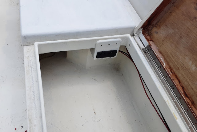
 I was surprised to learn that I had bought more outlets than I intended.  Outlets are now installed in both cockpit aft lockers.  These outlets could be used to charge the outboard batteries over a period of several days, but I consider this an unlikely event.  Lights and other rechargeable items could be plugged in and locked up while the boat is unattended.  I've developed a wish list for items I might leave plugged in here.  There are electric thrusters that strap onto your arm and pull you through the water like a one armed superman.  Electric air pumps allow you to stay submerged for extended periods.  These are just a few ideas if I should be on your Christmas list.

There is no shortage of available outlets.  The power available in this small solar system is sure to impose limitations on what can be accommodated from my wish list.  


Gluing jigs are sometimes necessary when assembling items.  Here the outlet boxes are surrounded by scrap wood screwed to the table to hold the pieces square.  Rubber bands provide a clamping force.  The scrap wood is covered with packing tape to prevent adhesion to the outlet boxes. 


I decided to deviate from the plans here and build a mast tabernacle.  I believe the tabernacle will provide a more stable configuration as I single handedly step (raise) the mast.    


The squared off section is the beginnings of a mast.  The tabernacle saddles the mast step on the forward cockpit crossbeam .  In time a clamp will be replaced with a through bolt after the tabernacle is epoxied together.  The mast will pivot on the through bolt as it is raised from a horizontal position to a vertical position. 

The plate facing the cockpit will receive hardware for handling the halyards (sail raising/lowering lines).  I await the hardware to complete the tabernacle in the next episode.


My remaining marine plywood is 3/8" thick.  I didn't feel like this thickness was enough for the loads encountered so two thickness were laminated together to achieve a 3/4" thickness.  Thanks to router patterning bits it is easy to turn out identical parts.

Not shown in this initial stage of the parts bearing the word master, is a square cut out that allows the mast to pivot to a horizontal position. 


Here the tabernacle parts are having six ounce fiberglass applied to the edges.  Push pins hold the fiberglass in place as the epoxy is brushed on.  Cuts are made on both sides of the fiberglass where there is a transition from a straight run to the curved section.  Epoxy is applied to the straight sections first to stabilize the fabric's position then the push pins are removed and additional side cuts are made along the curved section so the fabric will lay down against the piece.

The tabernacle "fork" pieces on the right hand side received stiffening from the application of 1708 fiberglass fabric on both faces.  1708 is a much heavier fabric that I applied in three layers to protect the keels in groundings.


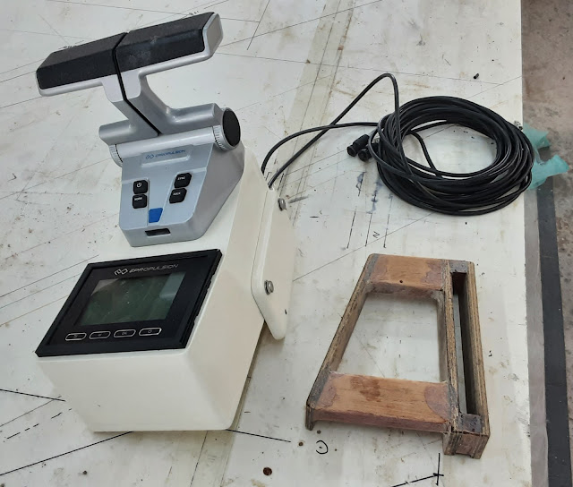
On the left is the electric outboard control unit.  The throttle levers are too stiff to operate without the unit being tied down.  In operation, this unit is held to the aft cockpit locker lid by a thumb screw.  The thumb screw goes through a hole in a plate extending below the control unit's base.  This plate does not allow the control unit to sit stable and flat when stowed away.  

To the right is the control unit stowage stand.  The slot receives the projecting plate and limits fore/aft and side to side movement.  The remaining elevated surface supports the control unit base.


Here the control unit rests on its' stowage stand just behind the motor battery.  This large locker is getting filled up before I'm even started.


Here we are again with gluing jig and the beginnings of the stowage stand.  What is different is a white template under the plastic that directs part alignment. 


Saturday, March 15, 2025

Bimini Me Not


 I'm running out of things to build, but an amount of work remains in a large list of small and important things.

 Above is the gaff spar.  This is a spar at the top of the sail that increases the sail area while reducing the sail height.  The reduced sail height lowers the sail's center of force thereby reducing the capsizing forces.  This is an old school type of a sail rig.  The banana shaped piece will be held between the forks by a pin and slide against the mast as the gaff/sail is raised or lowered.  It is shown here after fiber glassing and primer painting.  I await the sails to install additional hardware and the paint top coat.


Each gaff leg is a lamination of three thickness of mahogany, it is just too stiff to bend in a single thickness.  The legs were individually laminated while clamped to blocks screwed into the work table to form the desired shape.  Above, the legs are epoxied together to complete the gaff.  This is followed by rounding over the edges to fit comfortably into the sail sleeve.   

I've always thought that a bimini would be necessary to provide refuge from the intense sun.  My thinking was that this would come as a later addition.  I happened to come across a bimini at a price and color that I could not pass up.  It is far easier to make provisions for this now rather than later.


Initially the bimini frame was too large to be accommodated in the available space and it made access into the cabins more difficult.  After much consideration and frame cutting it was made to fit, but the supplied bimini fabric top may be scraped.  The top will be a future project to develop sewing skills for other projects to come.  The bimini will provide coverage for over 50% of the cockpit area.  One down side is that the mast will need to be extended so the sail will pass over the bimini.  This has been done on other Tiki 26s.  I'll just need to reef the sail at lower wind speeds than in the standard mast configuration.


The bimini stows away in the forward position leaving the cockpit and mast operations unobstructed.  Reasonable access to the forward trampoline, lockers and head are possible by this arrangement.  The burgundy bimini cover still fits in spite of my modifications.


No, these are not tasty treats.  The ingredients are mahogany, fiber glass, epoxy and fairing compound.  These are the raw bimini mounting blocks before they are sanded and adhered to the cabin sides.   In the background is part of a full scale bimini frame drawing and its' hinge points.  This drawing was very useful in determining the frame cut lengths.

It was not possible to hold the floppy bimini assembly in the installed position without mounts.  Interference with other necessities were not apparent until the bimini was in position.  The sheets control the jib sail position and the bimini frame limited the paths the sheets could take to control the sail.  Crippling the boat's sailing ability is not a viable option.  Much time and effort went into the bimini, but this arrangement will be abandoned.  All is not lost as the bimini may reappear, but be more like setting up a tent at some future time.


Notice anything new and different here?  That's right, 140 watts of solar power installed on the locker lids!  Each solar panel has a dedicated solar charge controller to keep the battery charged.  If one panel is shaded by the sail, the other panel can still provide charge current.  A third charge controller is installed that may service a future panel on the aft trampoline.


One difficulty that had to be overcome was the very stiff solar panel lead wires.  These wires are meant to endure constant sun exposure and do not allow tight bend radiuses.  Above are the holes the wires pass through in the locker lid.  Initially a straight hole was drilled through the lid and then a small rasp was worked through the holes at an angle so the wires could be installed in a more horizontal position.  


The solar panels and lead penetration covers are held on by Very High Bond (VHB) doubled sided tape.  It is said that VHB tape is used to install windows in skyscrapers.  It is a one shot installation with no post installation adjustments.  To insure good alinement wooden locating guides are taped to the lid before installation.


Here the panel is installed with the lead penetration covers.  The covers are installed at a distance from the panel that gives the tightest lead radius that I feel comfortable with.  This image may better illustrate the need for the nearly horizontal lid penetration holes previously discussed.

It seemed wise to do some heavy boat material shopping as tariff stupidity is bandied about.  The following items should be in my hands in the next month or so:
- Main sail with burgundy gaff sleeve, sail cover, sail number 449 and inverted Wharram logo (for those two readers who know the boat's name)
- Jib sail with burgundy furling strips on the foot and leech
- Roller furling jib foil
- 100 Ah 12V lithium battery
- Locker latches
- Primer and paint 

Sunday, January 19, 2025

Tillerating

 Anchor Locker

In a previous episode the anchor locker was featured in a paint primer state.  It has since been finished as you are soon to see.


This is view into the anchor locker with the anchor roller assembly to the left.  An over center latch, in the upper right, hooks onto the anchor chain to secure the anchor while stowed.  The cleat in the lower right serves as a backup securing point for the anchor rode (line) while anchored.  The anchor rode is attached to an anchor bridle extending from each bow as the primary attachment points.  Such an arrangement is necessary on catamarans to keep the boat from slewing back and fort relative to the wind.


   The anchor locker lid is hinged at two points so that it folds in half towards the aft end.  Two latches are installed adjacent to the center hinge ends to prevent the locker from being blown or washed open.


Above is the installed anchor locker with a nonskid lid surface.  I'm torn between really liking it and thinking it might be over the top.

 Swim Ladder/Cat Walk


Side rails are install on either side of the swim ladder.  These rails will serve as attachment points for the aft trampolines.  Hardware is installed on the rail, after crossbeam and ladder to raise or lower the ladder from the cockpit. 

Tillers


Now that the hurricane season has passed, the sun shade is re-erected.  The rudders are lashed onto the hulls to support the cantilevered tiller arms.  The tiller arms are reinforced with lashings fore and aft of the rudder heads.  The tiller bar joins the tiller arm ends at a comfortable arm rest height in the cockpit.


As with the crossbeams, the rudders are lashed to the hulls.  The rudder lashing are in a figure 8 pattern to form an effective hinge.


As the boat goes through a turn, the outside rudder travels through a larger radius circle than the inside rudder.  This requires a difference in deflection for the inside and outside rudders.  The geometry of curved tiller arms achieve this deflection differential.  This is similar to the steering on an automobile. 

The tiller arms are constructed of two lengths of 3/4" thick mahogany joined together at the cockpit end.  The 3/4" thick material is too stiff to readily bend so thinner laminations are used.  Blocks are screwed to the work table to clamp the arms into the desired shape as the epoxy sets.


The tiller bar pivots on pins installed in the tiller arm ends.  The pins must be inclined at the same angle as the rudder hinge angle in order to function without binding or breaking.  This was accomplished by drilling through a mahogany block at a square angle. The blocks were then cut at the required hinge angle before the blocks were epoxied to the arms.  The holes then served as a drilling guide to continue the holes into the tiller arms.  The heads were cut off two bolts and rounded over to serve as pivot pins when epoxied into the drilled holes.

The tiller arms are the only exterior components I have not sheathed in fiberglass.  It might have taken better than a week to complete such a process and I might have ended up with tiller arms that would no longer fit on the rudders.  The mahogany, two coats of epoxy and five coats of paint should offer good enough protection from the elements for a number of years.