Wednesday, January 31, 2024

Banjo Cases


Above is a start on the cockpit.  The material is honeycomb core fiberglass 4' x 8' panels.  Two panels were joined together with a mahogany spline to form the cockpit floor.  The floor was cut to finished dimensions of 77" x 96".  The sides are epoxied in place while clamped to keep everything square and straight. 

I don't enjoy working with this material as it has given me a case of fiberglass itch for the first time in this project.  Wearing flip flops and short sleeve shirts, while cutting this fiberglass material on a table saw says I was asking for a case of itch.

The panels came coated with white paint that did not stick well to epoxy so the paint had to be removed with a new belt sander.  The paint was removed where joins are made.  The paint was very difficult to remove, it must have been some great paint.


Cutting the panels slices through the honeycomb cells leaving voids in the cut surfaces.  The exposed cut surfaces can be filled with thicken epoxy to create a finished edge.

A person could look at the image above and wrongly ask, "Why the built-in banjo cases?"  I might look at the inquisitor askew and wonder how it is I come across as so hillbilly.

A pair of electric outboards will retract and fill the banjo cases.  There will be no visible indication that outboards are on board when retracted.  The battery placement is controlled by the power cord length extending from the outboard shaft.  I feel very lucky that the outboard equipment could be modified to suit my purposes.

A removable cover provides access to the retracted propeller in the event the anode needs changing, or the propeller needs to be cleared.  With the propeller lowered into the water and an improvised seat, this opening could serve as a backup to the composting toilet (may the day never come to pass).

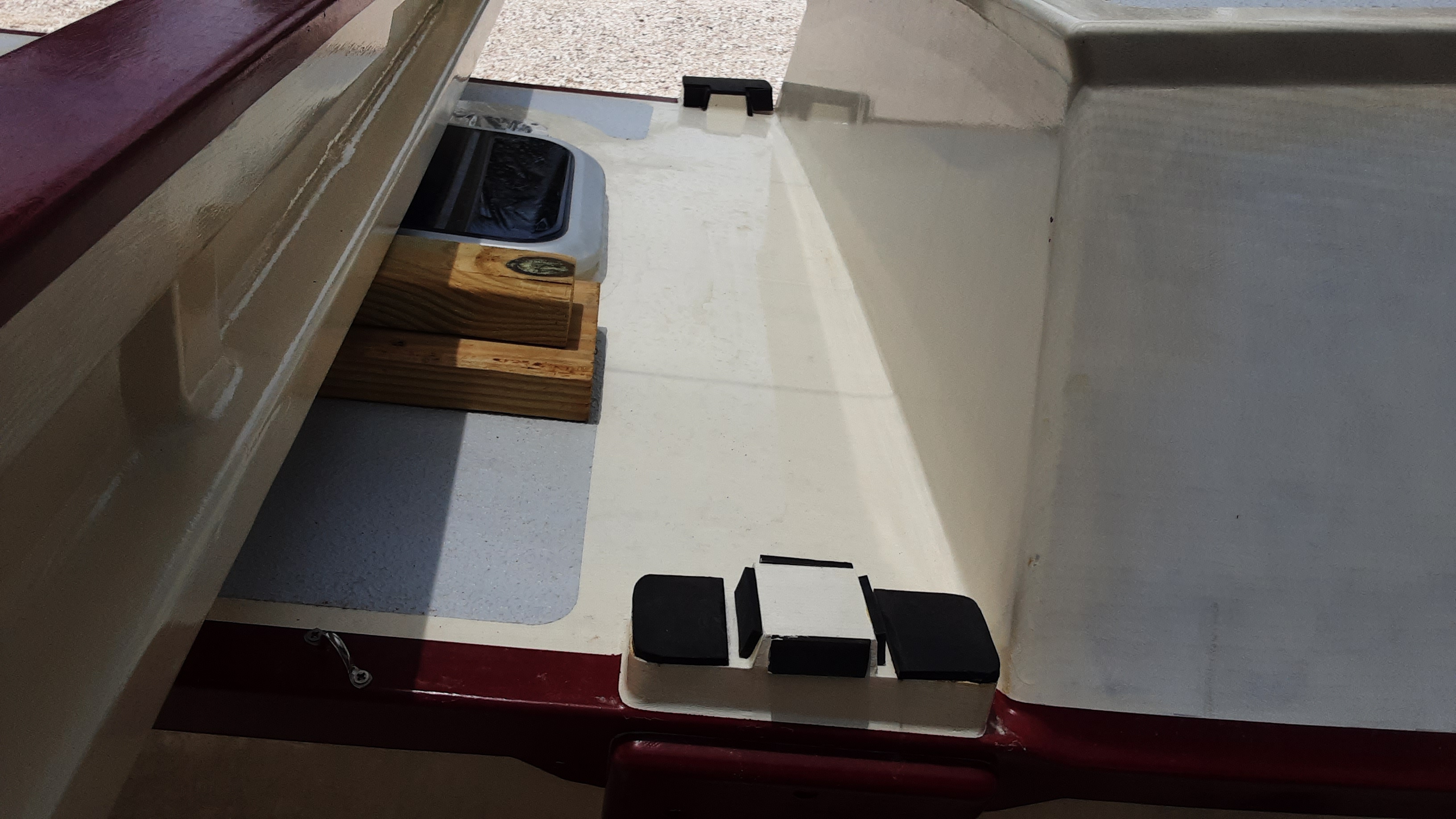
These simple parts may not seem like much, but many concepts were conceived, rejected and iterated on to distill into the above parts.  These parts will mount the motor batteries and a motor control connector.

To the right is the underside of the battery case.  Battery case slots engage with the two smaller mounts to prevent fore and aft movement.

The single aft mount lifts the battery end 1.5 inches so that the motor lead exits the battery in a more horizontal position to better accommodate the limited vertical space,

The motor mounting screws are positioned about midway through the cockpit floor thickness.  The motor mount gives the motor a downward thrust of five degrees and retracts the propeller to a position too high for the available space.  The motor mount, above, overcomes these obstacles.

Here the motor mounts are seen in profile with wedges added on the aft (right) face.  The wedges assure that the motor shaft is 90° to the cockpit floor.  The mounts are epoxied to the underside edge of a cut out in the cockpit floor to form a shallow pan below the cockpit.

The finial cockpit form emerges with the addition of the inner locker walls.  The motors and batteries are contained in the lockers below the cockpit seats.  The width required for outboard installation and the adjacent batteries compelled a 22 inch width to the cockpit seats.  The seat width is too much for comfortable sitting but is better for laying down on.  The wide seat might be the perfect spot for a comfortable bean bag chair.

Fillets and fiberglass are applied along the length to the joined panels.  Gaining access to the joined surfaces is much easier with the cockpit resting on its' side.  


The inner combings (walls to block water from entering lockers) complete the cockpit's major construction.  Notice that fore and aft are square sections spanning between the right and left lockers.  The square sections carry wiring around the entire cockpit perimeter.  This wiring will provide for the following:
- anchor and navigation lights
- outboard motor control signals
- fore and aft 12V DC and USB outlets
- transfer solar and battery power between hulls
- depth sounder output and power
 
A coat of primer and the cockpit will be ready for fitting.

Possibly you recognize the person in the picture who is about to board his vessel for the first time.

A friend helped with the cockpit install, the images and celebration.  Regular readers may recall the four wheeled single axel dolly used to move the hulls.  Two 2"x4"s repurposed the dolly into a rickshaw like device to hold the cockpit at the correct elevation to rest on and between the crossbeams.  Clearance between the hulls and cockpit is about 1/2 of an inch.  I was rather astonished at how well this contrivance worked; I'm thereby encouraged to try any wild ideas that may occur to me.  


Looks like wanta be boater boy is pleased with the new perch.  Shortly after this picture, about 10:00 am, was the occasion for the first ever cockpit cocktails.  It turned into a pleasant cockpit day with a constant breeze, shade and new surroundings to contemplate.  


A contribution slot to Davey Jones locker exists between the cockpit and the hulls.  Anything on board is sure to fall through these slots.


The cockpit/hull gap is characterized with a template.


This filler plate should limit Davey Jones's take and block or reduce water splashing up between the hulls and the cockpit.  The locker lids will mount to the filler plate bolted to the inner combings.

Sunday, October 1, 2023

Idling Too Long

September 2023 marks the sixth year of the boat build.  I can only claim progress for 3/4 of a year this September due to a lack of materials.  Materials ordered in July didn't arrive until the last of September as the result of ongoing shipping issues.  Having nowhere to go, no one to see and nothing to do I spent way too much time on a YouTube addiction.  My ship has just arrived so my normal boat building days can resume.

Two 70 watt solar panels have arrived.  Both panels will be installed on forward locker lids as shown above.  The combined output of 140 watts is not likely to provide enough power for much more than a day sail.  Provisions are made for a future larger solar panel accommodated on the aft trampoline for extended cruising.

Painting is in my future.

The anchor, bow rollers, and anchor rode (anchor chain and line) will not be in service for a while but are necessary to size, design and build an anchor locker.


Above are two of the four 4' by 8' sheets of honeycomb core fiberglass panels.  The cockpit will be built with these panels.  Two panels will be joined with a spline and cut to size to form the cockpit floor. 


I manage to make some progress in July before the lack of materials idled me.  Above is the top of one of the two electric outboards.  Normally the battery latches into the black battery mount.  The mount is composed of two halves that clamp around a tube preventing the shaft and lower propeller end from falling into the sea.  The normal arrangement is too tall to fit under the cockpit seats, so modifications are necessary to separate the battery mount from the clamp.
\

A dull hacksaw blade and persistence managed to separate the mount and clamp.  What do you suppose this operation would do to my warranty?  In any event the warranty will be expired before the outboards will see any action.


 The outboard is significantly shorter without the battery and mount attached.


A washboard closes up the hull entrance.  A plate, on top of the washboard, covers the raw wood groove in the image above.  Water enters the gaps between the plate and the opening to flow towards the interior due to the slope.  The groove slopes in the opposite direction to drain the water outside.  Rain initially proved this arrangement was not effective.  Reworking the groove has removed all concerns that water can enter the interior this way.  All passengers may sleep well and dry.


 The aft trampoline crossbeam is nearing completion.  On the right is a template used to cut out the plywood that is installed in its' place.  A batten, small sticks and a hot glue gun will build a template easy and quick.


The completed raw aft trampoline crossbeam is shown in its' place.  In time it will receive the same color scheme as the other crossbeams.  This crossbeam will not only support the trampoline, but a retractable boarding ladder as well.

Friday, May 26, 2023

Burgundy Curve Boat Works

 I am highly surprised to learn that most readers of this blog live in Brazil.  I have no idea of how that came to be and would be interested to read any comments on this matter.

The three major crossbeams have received tabs on the underside that will later be drilled to lace on the trampolines.  A little more priming and the crossbeams will be ready for ......


Some sanding, masking, painting and hardware mounting bring the crossbeams into a state of readiness for installation on the hulls. 


The hulls must be lifted onto the dolly to move them outside.  In the previous experience with this, the dolly wheels appeared to be overloaded.  Two additional wheels were added to the dolly to better handle the load.


3/16" neoprene is adhered to the crossbeam locating blocks so there is no wood-to-wood contact.


Pad eyes are installed along the hull's inboard edges as part of the trampoline lacing system.


Here the crossbeams are placed in position on the hulls under a sunscreen.  A good friend was very helpful extracting all this from the shop as well as erecting the sunscreen.  The forward crossbeam has lashings on the outboard ends to secure the crossbeam to the hull.  There is a shortage of lashing lines for the inboard and outboard positions on the remaining crossbeams.  

The shop is so much roomier now with all this moved outside.


This is the control panel for the dual electric outboards.  This control panel will be mounted inside the starboard hull near the companion way.  A person may operate the motors from inside the hull or from the cockpit.


I've repurposed the outboard shipping box as a mockup of the outboard cockpit installations.  The outboards will reside in cockpit seat/lockers located along the inboard side of each hull.  The seat/lockers will extend to the full eight-foot cockpit length, a length longer than the shipping box.  The box width is about right to accommodate both the outboard and the battery.  

The box bottom is cut out to allow the propeller and shaft to be tilted down into the water.  A wall will follow the cutout edge and a cover over the propeller and shaft will prevent water entry.  Two episodes ago (The Light of Day) the outboards were shown in their normal configuration with the battery mounted on the outboard shaft top.  This would not work for my application and the battery mount was cut off from the shaft.  No doubt this voided the warranty, but the warranty will run out long before these motors see the water.  The cutting provided a means to mount the battery within the locker as well as the only thing preventing the outboard from dropping into the ocean is the black shaft clamp located above the tilting mechanism.  The lack of the battery counterweight makes it difficult to lift the shaft and propeller from the water.  Some lever arrangement must be worked out to overcome this issue.

Partly visible at the image top is a cardboard outboard mockup.  This was much easier to hold up near a hull to work out any issues.


I think the color combinations are working out well and I had to include a little boat porn.  Some may mistakenly think this project is nearing completion.  The truth is there is there is much work left to do, but I may have completed the most time consuming and difficult parts at this point.

Saturday, March 18, 2023

Remove the Mask


The decks now sport a top side paint coating.  All this masking must mean significant changes are coming and I'm eager share ....

The shear stringers have received a burgundy paint coating to emphasize the sweeping curves.   This painting scheme will be carried over to the curving crossbeam tops once the paint supply is replenished.  This image was made in the early morning when the rising sun streams directly into the shop through the roll up door.  The result is an image that does not reflect the color combination accurately.  


Above is the bow end while the sun is setting.  The hatteras off white (a yellowish white) hull paint appears closer to the color seen, but the burgundy seems more ruby to the eye than shown here.  The upshot is that lighting in the shop and my tablet image taking skills are lacking to produce good color renderings.  Lighting seems to change the burgundy significantly.  I may not truly know what this color scheme really looks like until it is rolled outside.  As it is, I am pleased with the result.

The observant ones will notice that the decks have a light grey nonskid applied.  Are you among the observant ones? 


The forward deck has masking challenges with the conjunction of the crossbeam (not present), hatch and solar ventilator.


I use cutting templates to trim masking tape into the needed shapes.   The ventilator threads into the deck and clamps the template in place.  The two 3/4" pieces are placed against the ventilator to space out the template the correct distance.  The 90° curve template was made for the aft ventilators and no material was available for a 180° template.  Masking cuts had to be made in segments to produce the ~180° curve.

The small circular cutting template rounds corners where masking tape lines cross.   Rounded corners produce a more pleasing result.  Masking is the most time-consuming part of applying the nonskid.  Of course, sanding will be involved!  KiwiGrip nonskid is very easy to apply.  The nonskid is applied to a clean surface with a notched trowel.  A special opened holed foam roller is run over the surface to produce the desired texture.  The masking, which took the better part of a day to apply, is immediately ripped off, with satisfaction, to finish the nonskid application.


A friend helped with sanding primer on the crossbeams, a rudder, and the lashing pads shown above.  His help has saved me some weeks of work.  The lashing pads have the first coat of three burgundy coats.  Lately I've been using Scotch-Brite pads to abrade the surface between coats as shown here with the frosty surface appearance.


The finished lashing pads are in place along the shear stringer.  This image cannot convey what I would have called the money shot of this episode.  I often find myself enjoying this view for extended eye candy moments.  

The finish paint has been applied to both hulls with the exception of the inboard cabin sides.  The cabin sides will be modified in the future and are protected by primer for the mean time.  With this work completed I'm now able to begin installing the various bits of hardware that have been consuming space for several years.  Possibly, the shop disorder will slightly be diminished as a result.

What follows is straight up boat porn: