Wednesday, February 12, 2020

Interior Fitments

This episode marks another milestone.  All the Tiki 26 interior fitments are completed:


Above, the port galley compartment is fitted with a small shelf to the right of the companionway (steps).  A grey non skid coating awaits application to the companionway tread surfaces.  A little gray will spark things up in my mind's eye.  Below the shelf and tucked in the corner is a raceway leading wiring into the cockpit.  A screwed on panel provides access to pull wires through the hull's side.

Varnished mahogany edging completes the bulkheads and shelving edges.


For those readers who may have missed previous episodes, the stove is in the action position while resting on the footwell cover doing double duty as a table.  Can you find the footwell cover magnetically stowed in the previous image?


The starboard hull received an identical companionway, shelf and raceway as well as an extra shelf and table ledge.  

Areas above the shelves are not painted.  Installing the cabin sides will require fiberglass and epoxy in those areas.


The interior is not greatly detailed in the plans.  Hopefully I have anticipated most future needs with the interior fitments.  This portion of the project has required thought before plans could form.  It has presented awkward working and painting positions along with finicky fitups.  In short, completing the interior has been very time consuming.  Some people building these boats apply spar varnish to the interior as opposed to paint.  These folks have saved lots of time, but end up with a dark and dreary interior where I'm better pleased with a bright and cheery aspect.  This is partly a matter of how time pressed and patient a person is.  I live in Belize were patience is required, I'm retired, so my time pressure is only from the grim reaper.

I am pleased to pass this milestone and move on to more straightforward tasks that will close in the cabins (I can then declare another milestone) and lead to finishing the hull exteriors.  From what I have read, fairing (smoothing) a hull can be mind numbing work and I may long for the days of interior fitment, but today I'll doubt that.  Regular readers will know there is sanding in my future.

In closing this milestone celebration I offer  interior images to better illustrate the ground covered:

Starboard aft compartments prepared to receive aft deck.
Aft deck ready for installation

Forward Bunk
Starboard forward bunk ready to receive deck
Forward deck ready for installation

Starboard head compartment, sans head


Friday, January 10, 2020

Navigation/Engineering Station


Here a cut out is made to fit the black electrical switch mount resting in the rectangular cut out.  The oscillating multi-tool makes quick work of it.  It can make plunge cuts and flush cuts against a clamped on wooden straight edge to provide precisely located cuts.  You likely need a multi-tool, but may not know it yet.


The last mana shipment provided wiring terminals, shrink tubing, wire markers and other sundries needed to make progress on the wiring system.  Above, the three blue solar charge controller positives are wired to the battery via a fuse panel on the right.  Above the fuse panel is the negative terminal strip.  A heavy black cable connects it to the current measuring shunt before connecting to the battery negative terminal.  This arrangement makes it possible to measure and track all current entering or leaving the battery.  This measurement coupled with battery voltage enables the battery monitor to report the state of charge.


I'm a fan of the streamlined art deco style, some of that may have brushed off here.  Think back to some of the vacuum tube radios if you are old enough.

The charge controllers are enclosed behind the panel above.  This panel contains a shelf to support the removable navigation table spanning the hull width.  The upwardly angled, circular battery monitor is above the shelf on the right.  

The charge controllers will always be energized and producing heat.  Slots cut under the shelf and the two horizontal varnished pieces provide cooling ventilation for the energized equipment.


Here the navigation table is installed as far aft as possible.  This position permits a second person to sit more comfortably on the table's forward side.  Ideally, the second person would be someone you would enjoy tangling legs with beneath the table. 

I'm rather pleased with this navigation/engineering station.  There is room for a VHF radio installation in the blank space next to the switch panel if anyone is shopping for my next birthday present.


The aft bulkhead has received paint as well as varnished edge moldings.  This compartment in both hulls have unpainted inboard hull sides.  Companionway stairs provide interior access and will be located on the inboard side along with additional shelving.  These items remain to complete the interior fitments.  

The companionway's location is dependant on the main hatch location and configuration.  There is much to untangle here before a plan takes shape.


The center bulkhead has received paint as well as varnished edge mouldings.  As in the port hull, the starboard hull has a goose necked lamp, a 12 volt outlet as well as two USB outlets.  

Recent blog episodes have installed components long held side due to precursor operations.  Suddenly it seems, many interior areas are at or approaching the finished state.  It is gratifying for me to see this project starting to look like something, but still a long way from the completed state.  I'm newly encouraged to solder on.


Thursday, December 19, 2019

Sudden Assembly Event


A previous episode, Two Years In, discussed the above lashing pads through bolted to the sheer stringers.  The 16 lashing pads are closer to their finished state with rounded over corners/edges and epoxy filled through bolt holes.  In the foreground are the three drilling templates used to create the sheer stringer holes and now the matching lashing pad holes.

Each template has a fence screwed to one side, thereby precisely locating the holes relative to one lashing pad edge.  Lashing pad and template witness marks are aligned to position the pad correctly along the template fence.  A screw secures the pad to the template to assure accurate drilling and to later reattach the pads for final drilling.  Each hole is drilled three times, first to accurately locate the hole, then to enlarge the hole and finally drilling out the epoxy filling to 1/4" diameter.  

16 lashing pads, each with three holes drilled three times is drilling 144 holes.  Fortunately, 96 holes can be knocked out quickly with the templates and leave 48 oversized holes remaining.  With this many holes it is worthwhile to build a simple drilling aid.  A fence screwed to a plywood scrap then clamped to a drill press table sped up the drilling operations.  The fence was positioned to drill either the lashing pad top single hole or the lower two holes.  Lashing pad witness marks are aligned with those established along the fence.  Bing bang boom, a pile of holes is reduced to sawdust.  If done over more craftily; each hole would be drilled only twice.


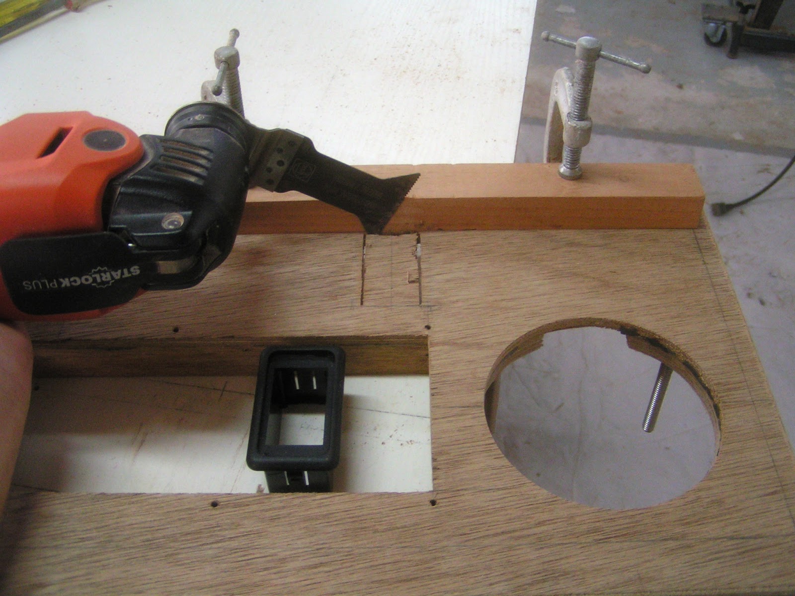
The two electrical panels are taking shape underneath the typical shelving.  The solar charge controllers are behind the left panel.  A battery monitor is mounted on the left panel face at navel level.  It would be difficult to read at that level so it is mounted on an inch and one half protrusion that angles the face up.  I have to say this tricky mounting didn't look right the first go round.  The plywood had been cut out and the mounting was too high up to look comfortable with the right panel components.  In the end it was lowered to provide a reasonably pleasing result.

Below the panel ends to the left and the right are wooden enclosures providing passages for wiring to the electrical components.  The left side will carry leads from the battery and the forward starboard solar panel.  The right side will carry the port and aft solar panel leads as well as the switched/fused circuit wiring to the remainder of the boat.  The wooden enclosures are certainly a cleaner installation than the plastic conduit used in the galley outlet.

 The right panel contains the battery disconnect switch and the fused switch panel.  The switch panel controls and protects the circuits through out the boat.  I'm awaiting the next monthly shipment for wire terminals, wire markers and an additional switch to wire, epoxy coat, install and paint this compartment.  Lately some progress has been limited by needed materials arriving in monthly shipments.  There is always something else that needs doing, but it's not wise to leave too much hanging.  Fortunately, the last shipment provided materials for stuff long hanging:


Grey non-skid is applied to the head floor and newly epoxied in step.  This KiwiGrip non-skid is easy to use, it is applied with a special texture roller and cleans up with water.  I'm considering this off white color scheme with the KiwiGrip grey for the decks.  I think this would be easy on the eyes in the harsh tropical sun.


Here we peer down into the cavernous forward locker.  The white paint ran out and it received only one patchy coat months ago.  A fresh can of paint and another coat takes it off the list of things long hanging.


Primer paint has not been available for a while and the deck undersides could not be painted until the mana shipment.  A different brand of primer was used that only required one coat of primer as opposed to two.  This reduced the between coat sands from 3 to 2.  Any reduction to sanding is a great boon in boat building.

The painted deck face above sits above the forward bunk compartment.  Painting is very time consuming requiring three to four coats with sanding in between.  Paint is only applied to the undersides above the bunks to reduce the required labor.  The deck undersides are otherwise protected by two epoxy coats.  The lime green masking tape is a preparation for installation.


The forward bunk compartment is masked off for deck installation.  Areas adjacent to the tape are slathered with epoxy then the deck is installed with screws, squeezing epoxy out onto the tape.  A tapered stick scrapes away and collects the excess epoxy.  The tape is then pulled away to leave a painted surface free of epoxy smears and blemishes, if all goes well.  The most frustrating part was trying to rid epoxy covered gloves of the just removed wadded up masking tape.


As some may have come to correctly suspect this is the much ballyhooed Sudden Assembly Event.  Most of the efforts above were in preparation for installing all the decks and the forward locker combings.  These parts have been occupying space and gathering long hanging dust for months on end.  

Gathering dust has also been a problem in the compartments covered by a deck.  It will never be easier to clean these compartments than before the decks are installed and efforts were so directed.  All openings to the decked areas are now covered in plastic in what may be a futile effort to keep the compartments dust free.

Earlier I thought installing the decks would reduce the shop chaos.  Getting to this point required a variety of processes and materials so that working space could not be found on the 29 foot long workbench.  A chaos eradication effort has cleared the bench with other such efforts to come.

The decks are not yet fully installed.  At this point the decks are just epoxied to the edge of the 1/4 inch hull panel.  A wedge shaped gap, as much as one inch deep, exists between the deck and the sheer stringer below.


Above, the hull is rotated on its' side so the wedge shaped gap is in a better working position.  The deck has been flush trimmed to the stringer below.  Thicken epoxy is loaded into a baggy with a corner cut off.  Squeezing the baggy fills the gap with epoxy and securely bonds the hull and deck.

Robot Army


In a former younger life, in a country far away I enjoyed a robotic lawn mower and a robotic vacuum cleaner.  These were cruder times of basicly bump and turn random navigation robots.  I enjoyed watching these machines go about their tasks while satisfied with the work completed.  In time the vacuum cleaner was revived once and later expired.  I suspect the lawn mower may have fared better.  

Generally the windows are left open here in Belize.  I find that, in spite of living near water, the house is dustier than I knew living all the years in the Washington desert.  No one in my single person household takes the time to take care of the floors.  The solution to this dilemma arrived with the last mana shipment, I suppose as an early Christmas for me.

The image above shows the beginnings of a robot army.  One is to vacuum and the other is to mop.  The vacuum is an iRobot S9+ with the super deluxe feature of a base station that sucks the robot's dustbin clean.  The first time the vacuum ran the robot returned to base station to empty the bin.  An error stopped this operation.  The robot's bin exit port was clogged with great wads of hair!  A person would think this was a house of nine cats, but it is only me; the still greatly follicled one.  This was a one time issue.

iRobot has evolved from the earlier bump/random path approach into systematic navigation.  These robots make overlapping straight line passes with alternate behaviors to deal with chair legs, etc.  The passes are made systematically starting at the base station mid house and working to the east then the east end adjoining rooms then moving to mid house and working west then the west adjoining rooms.  It is interesting to me seeing these robots accurately navigate through a room's door way then abruptly turn to start new cleaning passes. 

I've been withholding the sad tale of the iRobot Braava jet m6.  This machine does a terrific mopping job.  The mopping fluid is contained in a removable tank.  The fluid is sprayed ahead of the robot and the robot moves ahead and partly back three times as it progresses mopping across the floor.  It then backs up to spray again and repeating the mopping sequence.

The first time I installed the tank with mopping fluid it went in hard and didn't feel right.  I got two good mopping runs out of it and thought I would put some citric cleaner in the tank to ward off insects.  It seems to go OK the first time, but later I noticed it wasn't always spraying, the tank was leaking and the tank lid would not stay closed.  The tank was very difficult to remove from the robot.  The tank was broken and distorted.  It is hard to believe the spray pump suction could be so strong to damage the tank this way, but no other explanation occurs to me.  Replacement tanks are only found from vendors in Thailand and the U.K. in initial searches.  The lesson is sure to be not to blow off the instructions stating to use only their mopping fluids.

Random News

Three years in Belize and I've become a cold weather wimp.  If the coconut oil is frozen, it is too cold to take a shower.  If it is less than 70° F and a breeze is blowing through the house I seek to close windows, put on long pants and possibly a coat.  Please friends from the North write and say how you've shed tears for me during a snow shovel workout.

Poking around inside the electric scooter, by a stroke of luck, seems to correct the cogging issue previously mentioned.  The scooter was back on the road briefly before developing a new issue.  The rear brake caliper had seized reducing range, top speed and not to mention damaging the brake.  In time it was discovered a caliper piston had somehow received a nick that prevented it from retracting.  A little work with a file and fine sandpaper makes the scooter good to go whenever the weather is accomodating.

Friday, November 15, 2019

Let There Be Portlights


Heavy rains have expanded the across the street and recently mowed swamp to record size.  This is the source of frog serenades and an abundance of mosquitoes.  I suspect the five white egrets are seeking the frogs.  Possibly a dozen of these large egrets are roosting in the trees behind the house next door.  This is the first time this has happened in the nearly three years I've lived in my house.  The egrets have many vocalizations.  At dawn and dusk they get riled up and I'm treated with background sounds from old Tarzan movies.


The bow and stern cleats received 1/8" thick backing pads secured by screws to the deck undersides.  The 1/8" stainless steel flat bar material arrived on the last once a month shipment.  The decks are now one process away from installation.  The shipment arriving at months end will provide the primer/paint to apply before installation.  I look forward to an upcoming sudden assembly event!

Solar Charging System


The beginnings of the solar charging system is shown mounted on the starboard hull.  All of these components required wooden standoffs so the equipment mounting screws don't penetrate the hull.  A 100 amp hour battery will reside below the bunk in the painted compartment to the left.  The battery leads will pass through the bulkhead and then up through a hole (lower left in unpainted compartment) to connect to the charging system.  My estimated electrical loads are small.  The battery positive terminal is fused at 30 amps.  Smaller diameter and more flexible #6 battery leads are suitable in this low amperage arrangement.

A shunt is mounted in the upper left.  The battery negative lead attaches to the shunt's lower brass stud.  A lead from the shunt's upper brass stud will pass over the blue box tops and connect to the negative distribution buss mounted upper right.  The shunt measures all the current flowing into and out of the battery.  This is tracked by a battery monitor that displays the state of charge as well as other parameters.

The three blue boxes are MPPT (Maximum Power Point Tracker) charge controllers and said to be the most efficient type.  These receive input directly from the solar panels and adjust the voltage and current to match the battery's state of charge requirements.  Why three charge controllers you might ask?  The output of solar panels wired together is markedly reduced if any of the panels are shaded.  A boat with lines and sails is likely to be shading any one of the panels at any time.  At least one of the three panels should be able to do its' best when others are shaded. 

 To the right, below the negative distribution buss is a fuse block.  The battery positive attaches here with fused connections only to the charge controller's positive outputs.  The charging system is always energized, there is no on/off switch.  These charging components lay the groundwork for a disconnect and switched/fused circuits to come.    I await a future shipment of wire, lugs and other items to begin making connections.

Best of all, the battery monitor and charge controllers are equipped with bluetooth and an app.  I'm destined for a future of nerding out as partly demonstrated above.  Enough with nerding and on to things more visually stimulating ....


The outboard cabin sides are prepared for flush mounted portlights on internal mounting flanges.  Portlight sizes and shapes can do much to affect a boat's visual appeal.  I like the upward sweeping line of the shear.  The portlights' bottom cutout "mirrors" the shear sweep while the top cutouts follow the straight roof.  I think this has a pleasing aesthetic while blending the transition from curving to straight.  It is difficult to judge what is really aesthetically pleasing within the shop confines, Hopefully, shock and dismay will not be experienced when viewed at an all encompassing distance in the light of day.


There must be compliance in the portlight mounting method to accommodate the differences in plywood and acrylic thermal expansion rates.  This is accomplished by cutting the acrylic 1/8" smaller in dimension than the flush mount opening all around as well as using a 1/4" thick bedding adhesive.  The mounting flange face is positioned 1/4" away from the inside cabin face by plywood spacers to provide the bedding depth.  These spacers are cut to match the flush mount opening and the mounting flange's outside perimeter.  

The image above shows one set of mounting flanges screwed to the spacers as the epoxy sets.  Clear plastic tape covers the cabin side so the mounting flange/spacer assembly does not adhere to the cabin sides.  The cured epoxy assembly is unscrewed from the cabin side to machine round overs on  the outside and inside edges producing the finished result in the background. 


Regular readers may have noticed the cut outs for the aft opening portlights are made.  I think it is traditional to hinge opening portlights from the top.  There may be good reason for this, but I value my headroom so hinge on the bottom it is.   Plywood rings the portlight opening to stiffen things up.  This extra thickness flushes out the aluminum retaining ring giving the portlight less of a tacked on flavor, 


The port hull galley is mostly complete, but awaiting paint for the sink interior.  The goosenecked lamp is mounted to a box on the right bulkhead.  The box contains a 12 volt DC outlet as well as two USB outlets.  This is the only electrical service to the port hull,  The starboard hull will have a similar lamp and outlet arrangement.