Cockpit Changes

Above is the cockpit state from the last episode. Locker lids and cockpit to hull gap fillers are lacking.

The locker lids feature a strong box finger joint construction.

This is the join between segments of the hull to cockpit gap fillers. Plywood fingers epoxied to the undersides assure the segments present a flush surface. Locker lids (not shown above) are hinged to the gap fillers that are in turn bolted to the locker's inner combing. The gap fillers are segmented to make them easier to handle and less fragile when assembled with individual lids. All new components are given a single coat of white primer to protect the epoxy coatings from UV damage.

This is much more presentable cockpit with the lids and gap fillers in place. The gap fillers form a convenient sunken shelf next to the seats. Now the cockpit is established and has wiring runs all around the perimeter, it is time to install the electrical system.
Electrical System

Wire runs are provided in both hulls so that none of the wiring is exposed. Previous provisions made for electrical wiring to enter/exit the hulls were not high enough on the hulls to reach the cockpit. New holes were required on the shelf, the cabin side and the cockpit. The large black cable is a number 6 conductor that carries all the negative current for distribution throughout the cockpit.
Notice the upward sloping box shaped wire runs between the cockpit and the hull .......

Lashings join the hulls to the crossbeams so that mating parts can flex and relieve stress. Components must accommodate flexing in adjoining structures. The box shaped wire runs, imaged above, mount between the hull and the cockpit with a 1/4" clearance between the inner and outer box structures, thereby allowing flexing between components. The small box shape mounts lower against the hull than the larger box shape mounted on the cockpit. Any water splashed up into the gap must go up hill to be stopped by an inside lip on the large box opening. The water then drains out the gap it entered from below. That is my fine theory of how these flexible wire conduits will exclude interior water and hopefully, no plan B will come into play here.

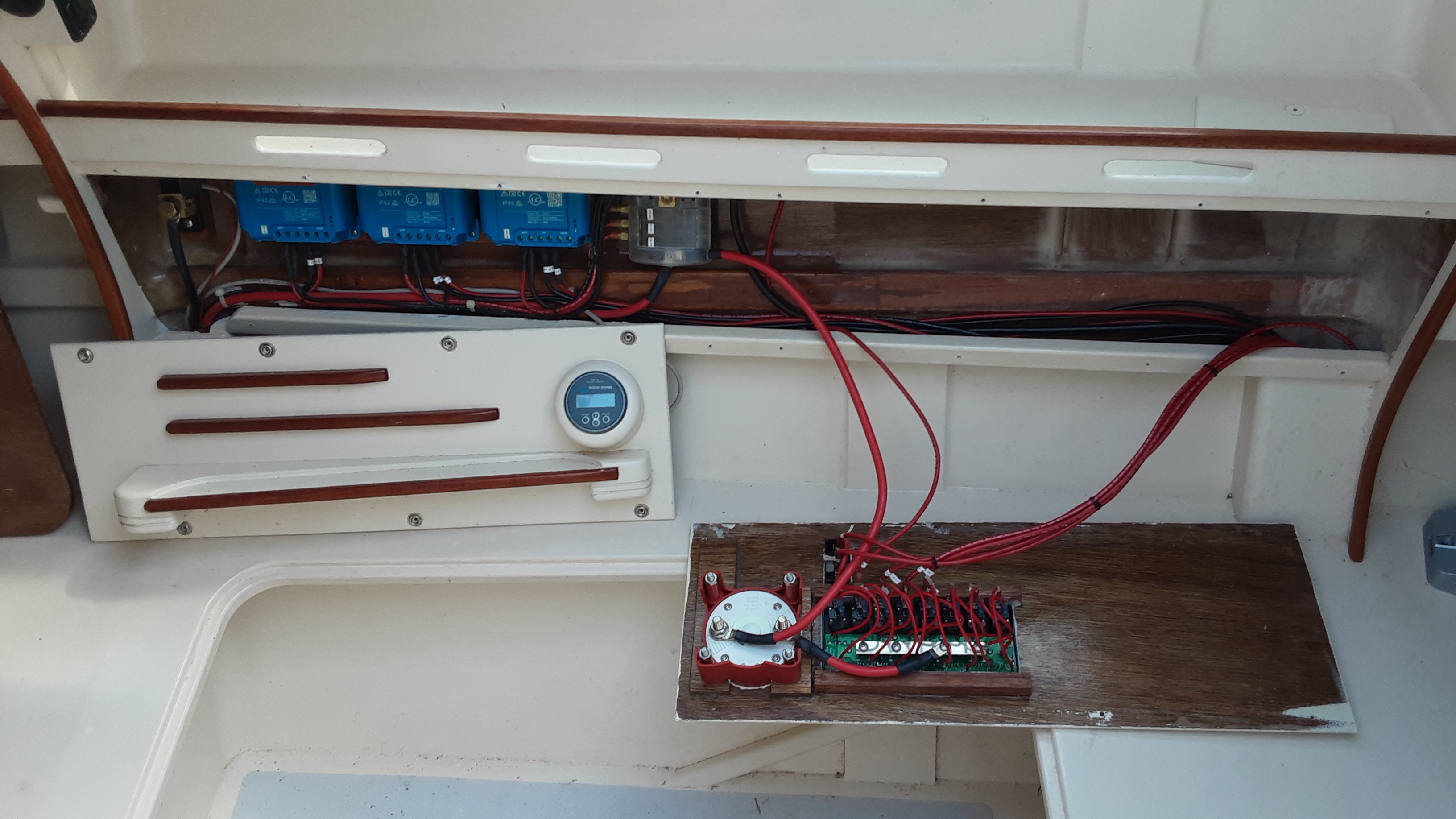
Here we are in the aft starboard cockpit locker where the power is distributed. At the top is the negative bus bar, below that is the positive termination panel for the switched loads and solar panel inputs. The electrical system will distribute auxiliary solar power, port solar power, port hull power, depth sounder, navigation/anchor lights and cockpit outlet loads. The black box to the left is a depth sounder that connects to my tablet based navigation software by blue tooth. All circuits are given numbers and number labels are applied to all terminations for a given circuit. This will prove helpful should trouble shooting be necessary in the future. A plexiglass guard for this area will be a good idea before power is applied.

New holes require new covers.
I haven't had a look behind these panels for a while. To the left are visible the three blue solar charge controllers. On the backside of the right panel is where switched/fused circuits will terminate.
Motor Controller

The electric outboard motor control panel has suffered a major change of concept. The initial plan was to mount the controller and display inside the starboard hull, but it was intrusive, not very useful when operating from the cockpit and would require hull and cockpit penetrations for the cabling.
Plan B is to mount the controller and display on a box that can be attached and removed from the locker lid. The throttles are very stiff to operate so that the controller box must be soundly attached to the operating surface. The details for this remain open. The cockpit lids inner and outer combings must be modified to allow passage of the control cables from the motors to the controller box. The controller box is stored in the locker when not in use.
New Locker

Can you name this assemblage?

Here it is in a more completed form.


A double hinged lid provides full access to the locker. The anchor locker will be held to the crossbeams by three lashings.
If you are in the boat, in the water won't it be kind of hard to reach over the closure to get what is in the Locker ?
ReplyDeleteDeb
Oops. Nevermind. The Locker is between thé trampolines...
ReplyDeleteDeb