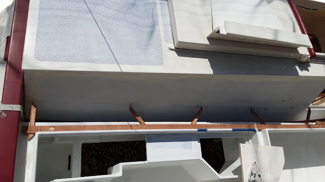
A person could look at the image above and wrongly ask, "Why the built-in banjo cases?" I might look at the inquisitor askew and wonder how it is I come across as so hillbilly.
A pair of electric outboards will retract and fill the banjo cases. There will be no visible indication that outboards are on board when retracted. The battery placement is controlled by the power cord length extending from the outboard shaft. I feel very lucky that the outboard equipment could be modified to suit my purposes.
A removable cover provides access to the retracted propeller in the event the anode needs changing, or the propeller needs to be cleared. With the propeller lowered into the water and an improvised seat, this opening could serve as a backup to the composting toilet (may the day never come to pass).
These simple parts may not seem like much, but many concepts were conceived, rejected and iterated on to distill into the above parts. These parts will mount the motor batteries and a motor control connector.
To the right is the underside of the battery case. Battery case slots engage with the two smaller mounts to prevent fore and aft movement.
The single aft mount lifts the battery end 1.5 inches so that the motor lead exits the battery in a more horizontal position to better accommodate the limited vertical space,
The motor mounting screws are positioned about midway through the cockpit floor thickness. The motor mount gives the motor a downward thrust of five degrees and retracts the propeller to a position too high for the available space. The motor mount, above, overcomes these obstacles.
Here the motor mounts are seen in profile with wedges added on the aft (right) face. The wedges assure that the motor shaft is 90° to the cockpit floor. The mounts are epoxied to the underside edge of a cut out in the cockpit floor to form a shallow pan below the cockpit.
The finial cockpit form emerges with the addition of the inner locker walls. The motors and batteries are contained in the lockers below the cockpit seats. The width required for outboard installation and the adjacent batteries compelled a 22 inch width to the cockpit seats. The seat width is too much for comfortable sitting but is better for laying down on. The wide seat might be the perfect spot for a comfortable bean bag chair.
Fillets and fiberglass are applied along the length to the joined panels. Gaining access to the joined surfaces is much easier with the cockpit resting on its' side.- anchor and navigation lights- outboard motor control signals- fore and aft 12V DC and USB outlets- transfer solar and battery power between hulls- depth sounder output and power
The cockpit/hull gap is characterized with a template.


