Friday, May 26, 2023

Burgundy Curve Boat Works

 I am highly surprised to learn that most readers of this blog live in Brazil.  I have no idea of how that came to be and would be interested to read any comments on this matter.

The three major crossbeams have received tabs on the underside that will later be drilled to lace on the trampolines.  A little more priming and the crossbeams will be ready for ......


Some sanding, masking, painting and hardware mounting bring the crossbeams into a state of readiness for installation on the hulls. 


The hulls must be lifted onto the dolly to move them outside.  In the previous experience with this, the dolly wheels appeared to be overloaded.  Two additional wheels were added to the dolly to better handle the load.


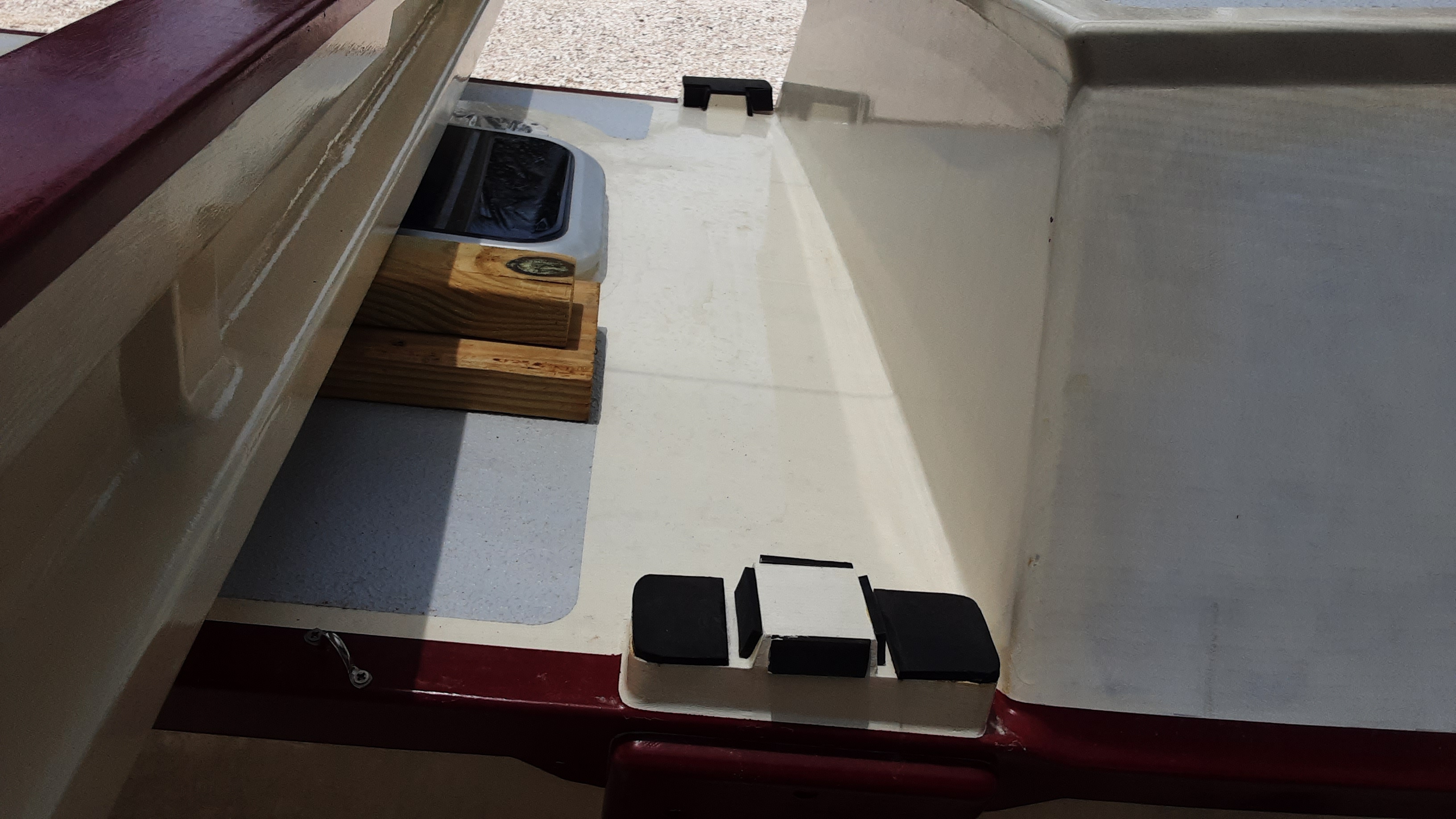
3/16" neoprene is adhered to the crossbeam locating blocks so there is no wood-to-wood contact.


Pad eyes are installed along the hull's inboard edges as part of the trampoline lacing system.


Here the crossbeams are placed in position on the hulls under a sunscreen.  A good friend was very helpful extracting all this from the shop as well as erecting the sunscreen.  The forward crossbeam has lashings on the outboard ends to secure the crossbeam to the hull.  There is a shortage of lashing lines for the inboard and outboard positions on the remaining crossbeams.  

The shop is so much roomier now with all this moved outside.


This is the control panel for the dual electric outboards.  This control panel will be mounted inside the starboard hull near the companion way.  A person may operate the motors from inside the hull or from the cockpit.


I've repurposed the outboard shipping box as a mockup of the outboard cockpit installations.  The outboards will reside in cockpit seat/lockers located along the inboard side of each hull.  The seat/lockers will extend to the full eight-foot cockpit length, a length longer than the shipping box.  The box width is about right to accommodate both the outboard and the battery.  

The box bottom is cut out to allow the propeller and shaft to be tilted down into the water.  A wall will follow the cutout edge and a cover over the propeller and shaft will prevent water entry.  Two episodes ago (The Light of Day) the outboards were shown in their normal configuration with the battery mounted on the outboard shaft top.  This would not work for my application and the battery mount was cut off from the shaft.  No doubt this voided the warranty, but the warranty will run out long before these motors see the water.  The cutting provided a means to mount the battery within the locker as well as the only thing preventing the outboard from dropping into the ocean is the black shaft clamp located above the tilting mechanism.  The lack of the battery counterweight makes it difficult to lift the shaft and propeller from the water.  Some lever arrangement must be worked out to overcome this issue.

Partly visible at the image top is a cardboard outboard mockup.  This was much easier to hold up near a hull to work out any issues.


I think the color combinations are working out well and I had to include a little boat porn.  Some may mistakenly think this project is nearing completion.  The truth is there is there is much work left to do, but I may have completed the most time consuming and difficult parts at this point.

Saturday, March 18, 2023

Remove the Mask


The decks now sport a top side paint coating.  All this masking must mean significant changes are coming and I'm eager share ....

The shear stringers have received a burgundy paint coating to emphasize the sweeping curves.   This painting scheme will be carried over to the curving crossbeam tops once the paint supply is replenished.  This image was made in the early morning when the rising sun streams directly into the shop through the roll up door.  The result is an image that does not reflect the color combination accurately.  


Above is the bow end while the sun is setting.  The hatteras off white (a yellowish white) hull paint appears closer to the color seen, but the burgundy seems more ruby to the eye than shown here.  The upshot is that lighting in the shop and my tablet image taking skills are lacking to produce good color renderings.  Lighting seems to change the burgundy significantly.  I may not truly know what this color scheme really looks like until it is rolled outside.  As it is, I am pleased with the result.

The observant ones will notice that the decks have a light grey nonskid applied.  Are you among the observant ones? 


The forward deck has masking challenges with the conjunction of the crossbeam (not present), hatch and solar ventilator.


I use cutting templates to trim masking tape into the needed shapes.   The ventilator threads into the deck and clamps the template in place.  The two 3/4" pieces are placed against the ventilator to space out the template the correct distance.  The 90° curve template was made for the aft ventilators and no material was available for a 180° template.  Masking cuts had to be made in segments to produce the ~180° curve.

The small circular cutting template rounds corners where masking tape lines cross.   Rounded corners produce a more pleasing result.  Masking is the most time-consuming part of applying the nonskid.  Of course, sanding will be involved!  KiwiGrip nonskid is very easy to apply.  The nonskid is applied to a clean surface with a notched trowel.  A special opened holed foam roller is run over the surface to produce the desired texture.  The masking, which took the better part of a day to apply, is immediately ripped off, with satisfaction, to finish the nonskid application.


A friend helped with sanding primer on the crossbeams, a rudder, and the lashing pads shown above.  His help has saved me some weeks of work.  The lashing pads have the first coat of three burgundy coats.  Lately I've been using Scotch-Brite pads to abrade the surface between coats as shown here with the frosty surface appearance.


The finished lashing pads are in place along the shear stringer.  This image cannot convey what I would have called the money shot of this episode.  I often find myself enjoying this view for extended eye candy moments.  

The finish paint has been applied to both hulls with the exception of the inboard cabin sides.  The cabin sides will be modified in the future and are protected by primer for the mean time.  With this work completed I'm now able to begin installing the various bits of hardware that have been consuming space for several years.  Possibly, the shop disorder will slightly be diminished as a result.

What follows is straight up boat porn:


Monday, January 30, 2023

The Light of Day


This pile of planer shavings should suggest to regular readers that my whining about the lack of materials may be over.

At long last, sealant has arrived to install the final portlight to make this hull weather tight.

The planed lumber provided material to complete the third crossbeam.  The beam is about to have the foreground fairing epoxied onto the beam face.  At this point the interior surfaces have received two epoxy coats, fillets on all joins and the areas to be joined are ... sanded.


This new beam will be installed forward of the mast.  It is unusual as the underside has an arc, where the other beams have flat bottoms.  I puzzle at a reason for this but can only concede that it looks cool.


The bows received some new bling in the form of chocks complementing the cleat.  The chock fasteners screw into the shear stringer.  As will all such fastenings, an oversize hole is drilled. filled with epoxy and later drilled out to accept the screw fastener.  Water and wood should not meet with this arrangement.


It is so dicey drilling next to an edge like this that a drilling jig seems wise.  The first hole is drilled using the jig and then a transfer punch is inserted through the jig and into the hole.  The "pinned" jig precisely locates the second drilled hole.  To the right of the pinned jig is the jig used with smaller diameter drill bits to drill out the epoxy filled holes to accept screws.


The port hull was the first to see the light of day.  My yellow wheeled dolly is a bit over loaded as the axel is bending so that both wheels were canted in towards the top.  This is the money shot for me as it is the first time I've been able to stand back and get a good overall view of the hull.

Beam Landing Pads


The dolly axel received some stiffening before the starboard hull was rolled out.  The distorted dolly wheels are at or near the limit of what they can support.  A fair amount of effort went into leveling and positioning the hulls.  A water level (water filled clear tubing) proved to be very effective for this task.  I was able to borrow a laser level to find my work and the laser agreed.  

The hulls and crossbeams are gathered here to be joined.  The beams are lashed to inboard and outboard hull sides.  The curving decks must be fitted with beam landing pads to transfer lashing compression loads between the beams and the hulls.  The landing pads need features that prevent the beams moving fore and aft or side to side.

Measurements between the beam and hull indicated compound angled cuts on the landing pad raw stock.  I found that making a shallow cut all around the cut's permitter helps to guide the hand saw on these tricky cuts.


A fair number of parts were required to mount the crossbeams.  The mounting parts above have just been fiberglassed.  There are many sharp edges on these parts that the fiberglass cannot bend around.  The fabric tends to stretch and move around as the epoxy is applied.  This feature makes cutting fabric to an exact size to butt up against an adjacent fiberglass face can be a futile exercise.  The sharp angle faces must be fiberglassed one at a time before continuing to adjacent faces.


The next day the excess fiberglass edges are trimmed and it is time for another round of fiberglassing.  Some of these items took three rounds of fiberglassing to complete.


The plans do not provide great landing pad details so a person must improvise.  Above is the underside end of the mast crossbeam.  The raw wood face with lettering is the landing pad face that will be epoxied to the hull.  The landing pad and the beam's locating features are separated by 3/16" thick neoprene to prevent the wooden parts from working against each other.  The locating faces are angled so the beam and hull will mate and de-mate readily.  This landing pad resists fore and aft motion as well as beam motion in the outboard direction.

The inboard landing pads must span a valley between the fore and aft edges.  The sloping valley edges and the sloping edges of blocks glued into the valley will receive the shape of a truncated pyramid mounted on the top of landing pad resting to the right.  Once the landing pads are painted, all neoprene pads will be adhered to the landing pads.  This landing pad arrangement resists fore/aft and inboard/outboard beam motion relative to the hulls. 

The hulls and beams can now be joined to each other, but everything must be dismantled and moved inside for finishing and other work.  I added all the gingerbread fittings to take this image before disassembly.  Can you spot the gingerbread before it is detailed in the next paragraph?

I'm impressed if you were able to spot any gingerbread crumbs.  There are cleats on the bow and stern as well as on the ends of two beams.  Did you spot the bow chocks?  Solar powered ventilators are found forward and aft of the cleated beams.  I still think these ventilators are a bit garish with the optional shiny stainless steel shell.  I attempted to remove the garish shell but found that it was adhered to the white shell underneath.  I may not learn to love it, but I can learn to live with it.

The Future is Electric


Electric propulsion is an emerging trend in sailing vessels.  I'm embracing this future.  My electric outboards ordered in middle November have arrived late in January after the Christmas shipping break and the Department of Fisheries got their fees figured out.  These three horse power Epropulson motors will be installed in lockers under the cockpit seats.  The motor's overall height must be reduced to accomplish this.  A great height reduction is to relocate the clip-on floating batteries to mounting locations within the lockers.  It is also necessary to also remove the black battery clip-on fixture at the motor's top to gain the needed clearance.  Initial examinations suggest this will work out very well.  The shop is filled with the new yellow wheeled dolly, crossbeams, lumber and an increasing state of disorder.  This disorder now creeps into my living space as there is no room for the outboards in the shop.

These motors will recharge the batteries while under sail.  The motors may be retracted, to reduce drag, once a charge is achieved.  A folding solar array is offered as an accessory to charge/supplement the battery.  Two motors will enable the boat to spin within its' own length.  This maneuverability is highly desirable to negotiate the 90° canal turn to reach the bay.  I need only to press an on button rather than repeatedly pulling a start cord to get going.  Gasoline fires and engine noise will not be a possibility.  These outboards are substantial and well made.  I'm happy and excited to arrive at this arrangement.

Friday, September 30, 2022

Poof, Another Year has Passed

September 2022 arrives to mark this project's fifth year.  The worldwide shipping slow down and lack of available lumber has stymied my ambition to move the hulls outside and make provisions to mount the cross beams.  This is a phase in the project I'm excited to experience as it will give a scale to the project's finished size.  The lack of materials from the late shipment has prevented the last portlight from being installed so the port hull is not yet weather tight.  I've been scrounging for smaller jobs that have been put off for a while as a means to continue progress and to add refinements.

The gally sink drain plumbing is now complete.

The wiring for the port 12 volt and USB outlets as well as the gooseneck lamp is completed.  Some challenges were imposed by the heavy #10 wire used throughout the vessel.  The wooden outlet enclosure was just deep enough to allow the heavy wires to make the backside connections and bend as required to follow the wire conduit.  Solar cell leads were also installed in the conduit run used by the lamp and outlet.  The solar cells dictated the #10 tinned wires used throughout.  The large wire minimizes the voltage drop/waisted energy going into or from the battery.

Finishes

All the bunk locker panels received a sanding and two coats of varnish.  The varnish was applied over two epoxy coats.  The varnish protects the epoxy from sun degradation.  Varnish is so much easier than topside paint.  Note the two panels in the right foreground.  These panels are marked with a P and an S to denote port and starboard.  These two panels can serve as interior tables spanning the respective hull's width.  The panels' geometry and mounting fixture's fit vary enough that these panels must be identified.  These are the two panels with corner embedded magnets to securely stole the panels when not in use. 

The main hatches and wash boards receive two coats of high build primer on interior surfaces.  A new round of sanding awaits.... In a few months, cooler temperatures should give better topside paint results on these interior surfaces.

Companion Way, Washboards and Hatches

Above is the aft edge of the companion way opening.  The house (cabin) top slopes forward and towards the outboard side.  Any water leaking past the closed companion way is likely to collect in the corner and leak into the interior.  A groove is cut into the opening to encourage water to flow downhill and drain the corner.
The elevated washboard has been fitted with tapered projections that fit into the grooves when fully closed.
With the washboard seated and the hatch closed. the grooves are nearly filled by the projections.  The idea is that surface tension in the narrow space remaining in the grooves will help wick the water away.  It remains to be seen if this arrangement has any merit.
The washboard is hanging across from the companion way opening, but the real foreground subjects are the new ears located near the opening's top.  The ears help align the washboard edges into the grooves on either opening side.  
The hatch track is stamped from sheet metal and had many razor sharp edges offering chances of severe cuts.  The tracks were removed, and the edges received a rounding over with a file and 220 grit sandpaper.  The tracks were permanently installed by coating the screw holes with penetrating epoxy before inserting the screws.  The numerous track screw holes did not receive the normal arrangement of threading into an oversized, cured epoxy filled hole.  

Paint pulled off with the track and compromised the painted protection underneath.  Penetrating epoxy was applied to these areas to protect the underlying wood from water.  I would say the hatches slide better now than ever!

Crossbeams

The crossbeams, fore and aft of the cockpit, received two primer coats.  The mast supporting crossbeam is shown upside down in the background.

The mast crossbeam now sports a dolphin striker.  The dolphin striker counteracts the mast compressive forces imposed on the beam.  Above, the green fishing line shows the path a cable would take to anchors near the crossbeam ends.  Tension in the cable creates an upward force counteracting the mast's downward force.

3/4" x 3/4" lumber strips are applied at the underside beam opening ends.  Theses openings now present a flat surface around each opening.  This enables the use of flat screens to exclude nesting insects.  Bees have already made an effort to take over my bathroom sink cabinet.  It is good to pare down things that may cause worry.

The aft trampoline crossbeam web is in the foreground with the forward crossbeam web and bottom flange in the background.  Progress on the forward crossbeam is limited to epoxying a 3/4" x 3/4" stringer along the curving bottom flange edge.  The lack of suitable lumber to complete these beams has thrown a roadblock in moving this project outside for assembly. 

Mast

The beginnings of a mast.  A subscale PVC pipe stands in for the mast to show the component's relative positions.  The four, hook like, mast cleats are located near the mast top.  They provide anchor points for stays that loop around the mast and anchor to the outboard hull cleats as well as the forward hull bridal.  

The hot dog bun shaped component is the gaff slider.  A gaff is a boom located at a sail's top or head.  The gaff slider slides along the mast as the gaff and sail is raised or lowered.  Leather is traditionally used on the sliding surfaces, but I used material cut from a plastic cutting board.  The plastic cutting board should provide a low friction surface and prevent scarring of a painted mast surface.  I've hung a sample of the cutting board material outside to test how it will endure the tropical sun for a year or so.  It remains to be seen if this is a good idea or not.

Step Ladder

In keeping with the desire to get this project outdoors, I built a step ladder for gaining access to the boat's interior and future cockpit.  In the foreground is a chair and a clamping worktable.  These items were my only means of obtaining boat interior access.  This arrangement has three steps to get to a level high enough to step inside.  The step ladder reduces the congestion at the narrowest point in the passage between the hulls.  I will not have to move my worktable and chair in and out of the weather in the future.

The top step received a modification to discourage its' use as an unstable step and to provide foot clearance when stepping into the hull.  The bulk of the step ladder's material is mahogany with scraps of my shipping crates thrown in.  The mahogany had too much undesirable sap wood to be used in the boat and took up floor space that I have reclaimed. 

I'm pleased to learn that the shipment departing Los Angeles August 8th should be in Corozal for distribution October 5th, hurricanes permitting.  There must have been problems along the way.